Supercharge Your Innovation With Domain-Expert AI Agents!

Boost apparatus with integration of ocp detection and ovp detection

a technology of ocp detection and booster apparatus, applied in the direction of electric variable regulation, process and machine control, instruments, etc., can solve the problems of increasing chip (ic) cost and corresponding increase so as to reduce the number of pins of control chips and lower chip cost

Inactive Publication Date: 2017-02-02
BEYOND INNOVATION TECH
View PDF2 Cites 3 Cited by
  • Summary
  • Abstract
  • Description
  • Claims
  • Application Information

AI Technical Summary

Benefits of technology

[0014]Based on the above, in the exemplary embodiments of the invention, since the OCP detection and the OVP detection of the boost apparatus are performed/executed when the PWM signal is respectively enabled and disabled, the control chip can achieve OCP

Problems solved by technology

Under such conditions, if additional circuit functions are to be provided to the boost apparatus, then the quantit

Method used


Image

  • Boost apparatus with integration of ocp detection and ovp detection
  • Boost apparatus with integration of ocp detection and ovp detection
  • Boost apparatus with integration of ocp detection and ovp detection

Examples


Embodiment Construction

[0020]Descriptions of the invention are given with reference to the exemplary embodiments illustrated with accompanied drawings. In addition, whenever possible, elements / components having the same reference numerals represent the same or similar parts in the figures and the embodiments.

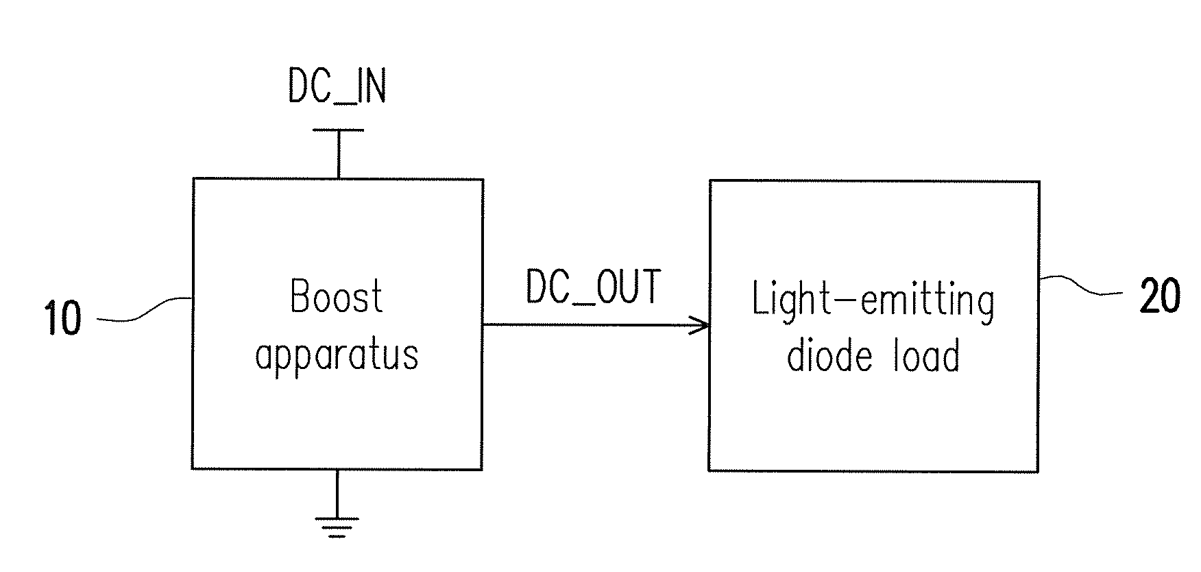
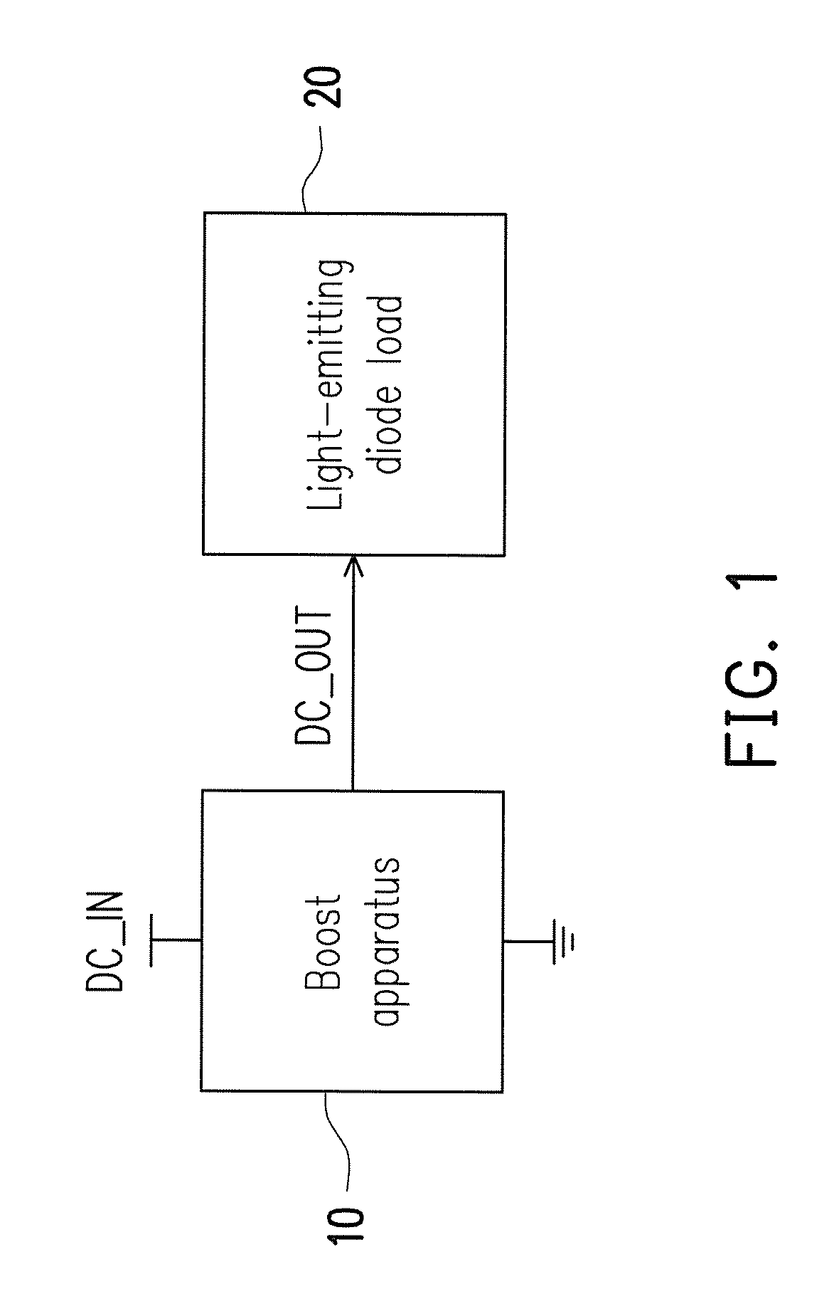
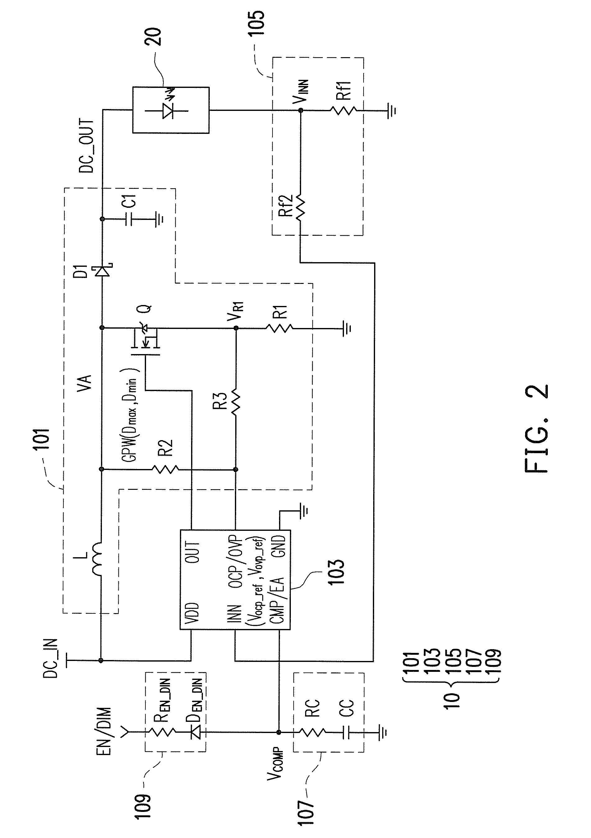
[0021]FIG. 1 shows a system block diagram of a boost apparatus 10 of an exemplary embodiment of the invention, and FIG. 2 shows an implementation schematic of the boost apparatus 10 of FIG. 1. Referring to both FIG. 1 and FIG. 2, the boost apparatus 10 is suitable for providing a DC output voltage DC_OUT to any type of load, such as: a light-emitting diode (LED) load 20, but is not limited thereto. The boost apparatus 10 may include: a boost power conversion circuit 101, a control chip 103, a feedback circuit 105, a resistor-capacitor (RC) network 107, and an enable / dimming circuit 109.

[0022]In the present exemplary embodiment, the boost power conversion circuit 101 can be configured to receive a DC i...


PUM


Abstract

A boost apparatus including a boost power conversion circuit and a control chip is provided. The boost power conversion circuit is configured to receive a DC input voltage and provide a DC output voltage to a light-emitting-diode (LED) load in response to a pulse-width-modulation (PWM) signal. The control chip has a first complex function pin, and is configured to: generate the PWM signal to control the operation of the boost power conversion circuit; perform an OCP detection on the boost power conversion circuit through the first complex function pin when the PWM signal is enabled to determine whether to activate an OCP mechanism; and perform an OVP detection on the boost power conversion circuit through the first complex function pin when the PWM signal is disabled to determine whether to activate an OVP mechanism.

Description

CROSS-REFERENCE TO RELATED APPLICATION[0001]This application claims the priority benefit of Taiwan application serial no. 104124811, filed on Jul. 30, 2015. The entirety of the above-mentioned patent application is hereby incorporated by reference herein and made a part of this specification.BACKGROUND OF THE INVENTION[0002]Field of the Invention[0003]The invention relates to a power conversion and supply technique, and more particularly, to a boost apparatus with integration of OCP detection and OVP detection.[0004]Description of Related Art[0005]The current pulse-width modulation (PWM-based) boost apparatus can be configured to provide a DC output voltage to a load, and the control chip therein generally has two independent detection pins to respectively and independently detect whether over-current phenomenon and over-voltage phenomenon occur to the boost apparatus, so as to determine whether to activate the corresponding over-current protection mechanism and over-voltage protect...

Claims


Application Information

Patent Timeline
IPC IPC(8): H05B33/08H02H9/00H05B44/00
CPCH05B33/089H02H9/00H05B33/0815G05F1/46G05F1/565H05B45/10H05B45/38H05B47/24H05B47/25Y02B20/30
Inventor LIN, CHIU-YUANHUNG, CHIEN-PANGKAO, CHEN-LUNG
Owner BEYOND INNOVATION TECH
Features
  • R&D
  • Intellectual Property
  • Life Sciences
  • Materials
  • Tech Scout
  • Unparalleled Data Quality
  • Higher Quality Content
  • 60% Fewer Hallucinations
Learn More