
Guide Roller Of A Pair Of Feed Rollers Of A Granulating Device

a technology of granulating device and guide roller, which is applied in the direction of shaft and bearing, grain treatment, thin material processing, etc., can solve the problems of large recoating effort of the entire guide roller, transportation and storage costs, installation costs, etc., and achieves the effect of facilitating pulling off or pushing and easing the pulling off or pushing

Inactive Publication Date: 2017-02-09
MAAG AUTOMATIK GMBH
View PDF1 Cites 2 Cited by
  • Summary
  • Abstract
  • Description
  • Claims
  • Application Information

AI Technical Summary

Benefits of technology

The invention aims to solve the problems of the prior art by creating a guide roller that can save transport and storage costs when replacing guide rollers with an outer hard rubber layer.

Problems solved by technology

Nonetheless, the various guide rollers have in common that in the event of wear of the hard rubber layer, be it with or without longitudinal slots and longitudinal webs, the entire guide roller must be recoated at great effort.
In this process, not only are installation costs incurred in uninstalling the guide roller to be replaced and installing a newly coated guide roller, but also transport costs and storage costs, especially since multiple feed rollers are in circulation for removal of used hard rubber layers and for the construction of new hard rubber layers.
However, this option for compensating the unevenness of joint locations does not exist for guide rollers of a granulating device having an outer hard rubber layer, for which it is necessary to remove the remaining layer at the end of the service life of the hard rubber layer and typically vulcanize a new hard rubber layer onto a cylindrical metallic core.

Method used


Image

  • Guide Roller Of A Pair Of Feed Rollers Of A Granulating Device
  • Guide Roller Of A Pair Of Feed Rollers Of A Granulating Device
  • Guide Roller Of A Pair Of Feed Rollers Of A Granulating Device

Examples


first embodiment

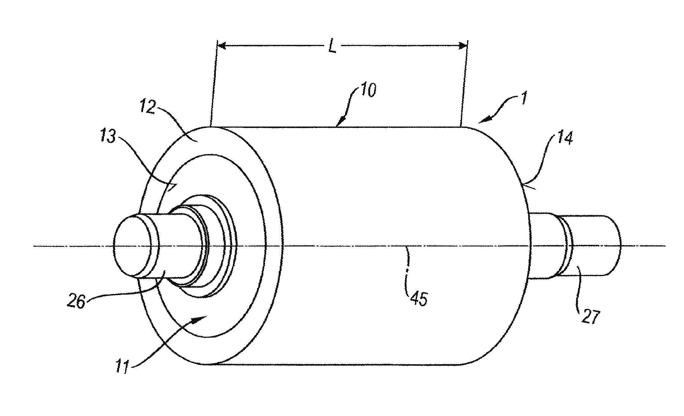
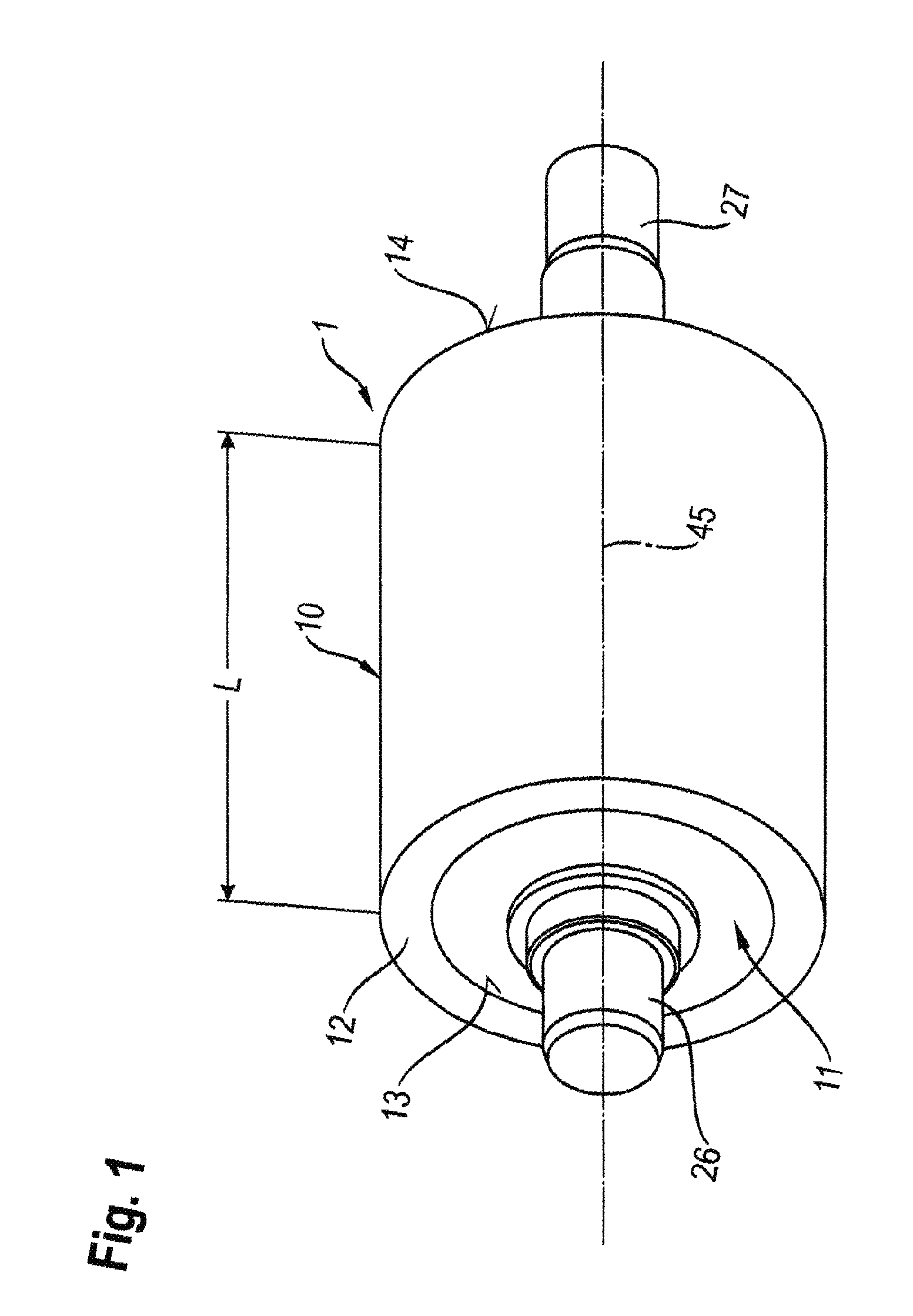
[0042]FIG. 1 shows a schematic perspective outside view of a guide roller 1 with replaceable outer hard rubber layer 12 according to the invention. The outer hard rubber layer 12 forms a sleeve 10 that is arranged on a core 11 of the guide roller 1 such that it can be pulled on or pushed off. For this purpose, the outer hard rubber layer 12 covers the entire roller width L coaxially to the axis 45 of the guide roller 1. FIG. 1 also shows a first end region 13 with a first journal 26 and a second end region 14 with a second journal 27, wherein the journals 26 and 27 project from the lateral end regions 13 and 14, for example in order to pivotably support the guide roller 1 in a granulator housing.

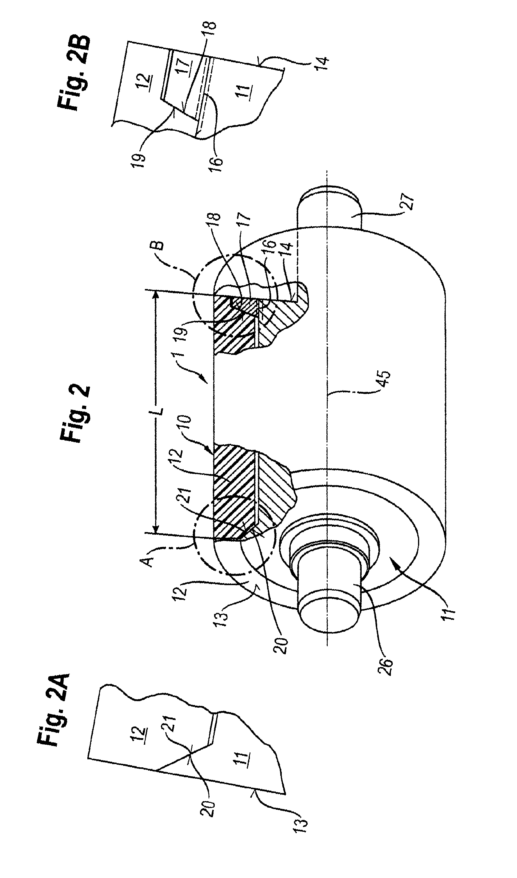
[0043]FIG. 2 shows a schematic perspective view of the guide roller 1 from FIG. 1 with regions partially shown in longitudinal cross-section. The regions A and B of the guide roller 1 partially in longitudinal cross-section illustrate the internal structure and the components that make it po...

second embodiment

[0049]Moreover, FIG. 4 also shows that, in this second embodiment of the invention, the key 22 projecting from the outer shell of the core 11 is now arranged in a longitudinal groove 23 that is located substantially or even completely in the reinforcing cylinder 44.

third embodiment

[0050]FIG. 5 shows a perspective view, with a region in partial longitudinal cross-section, of a guide roller 3 with replaceable outer hard rubber layer 12 according to the invention. In this embodiment, a modified reinforcing cylinder 44 is employed, onto which the hard rubber layer 12 is vulcanized. In the axial direction, the reinforcing cylinder 44 has an internal cone 24 in the longitudinal direction with an angle of inclination a between 1°≦α≦5° relative to the axis 45 of the guide roller 3. The sleeve 10 consisting of the hard rubber layer 12 and reinforcing cylinder 44 is arranged on an external cone 25 of the core 11 with an appropriately matched angle of inclination 1°≦α≦5°. For axial securing, as shown in FIG. 5, the ring nut 17 is once again placed on the thread 16 in the end region 14 with the conical surface 18 that cooperates with the mating conical surface 19 in order to axially secure the hard rubber layer 12 that forms the sleeve 10 with conical reinforcing cylinde...


PUM

PropertyMeasurementUnit
Compressibilityaaaaaaaaaa

Abstract

Guide roller of a pair of feed rollers of a granulating device for plastic strands, wherein the guide roller has a core and at least one outer hard rubber layer, wherein the at least one outer hard rubber layer forms a sleeve that can be pushed onto the core of the guide roller and pulled off of the core.

Description

FIELD OF THE INVENTION[0001]The invention concerns a guide roller of a pair of feed rollers of a granulating device for plastic strands. The guide roller has a core and at least one outer hard rubber layer.BACKGROUND OF THE INVENTION[0002]From the document EP 0 013 575 A1, a granulator is known for granulating plastic strands that has such a pair of feed rollers, wherein the rollers of the pair of feed rollers have lateral surfaces made of steel. In contrast to this application, granulating devices with such a pair of feed rollers usually have a drive roller and a guide roller. In this design, the drive roller can certainly have lateral surfaces made of steel.[0003]The guide roller, which feeds the plastic strands of the granulating device to the granulator, for example by pressing down the plastic strands, usually has a core, however, and at least one outer hard rubber layer, such as is known from the document DE 197 01 926 C2, although in this document the outer hard rubber layer ...

Claims


Application Information

Patent Timeline
IPC IPC(8): B02C18/22B65H20/02B29B9/06F16C13/00
CPCB02C18/2283B29B9/06B65H20/02F16C13/00B65H51/10
Inventor WILLEMSEN, THOMAS
Owner MAAG AUTOMATIK GMBH
Learn More