

Lubrication system with supply line monitoring
- Summary
- Abstract
- Description
- Claims
- Application Information
AI Technical Summary
Benefits of technology
Problems solved by technology
Method used
Image

Examples
Embodiment Construction
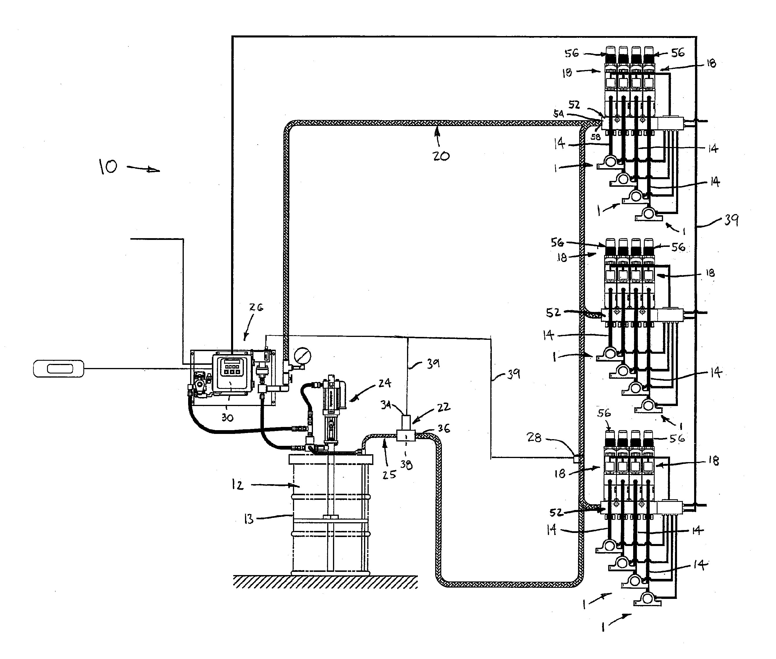
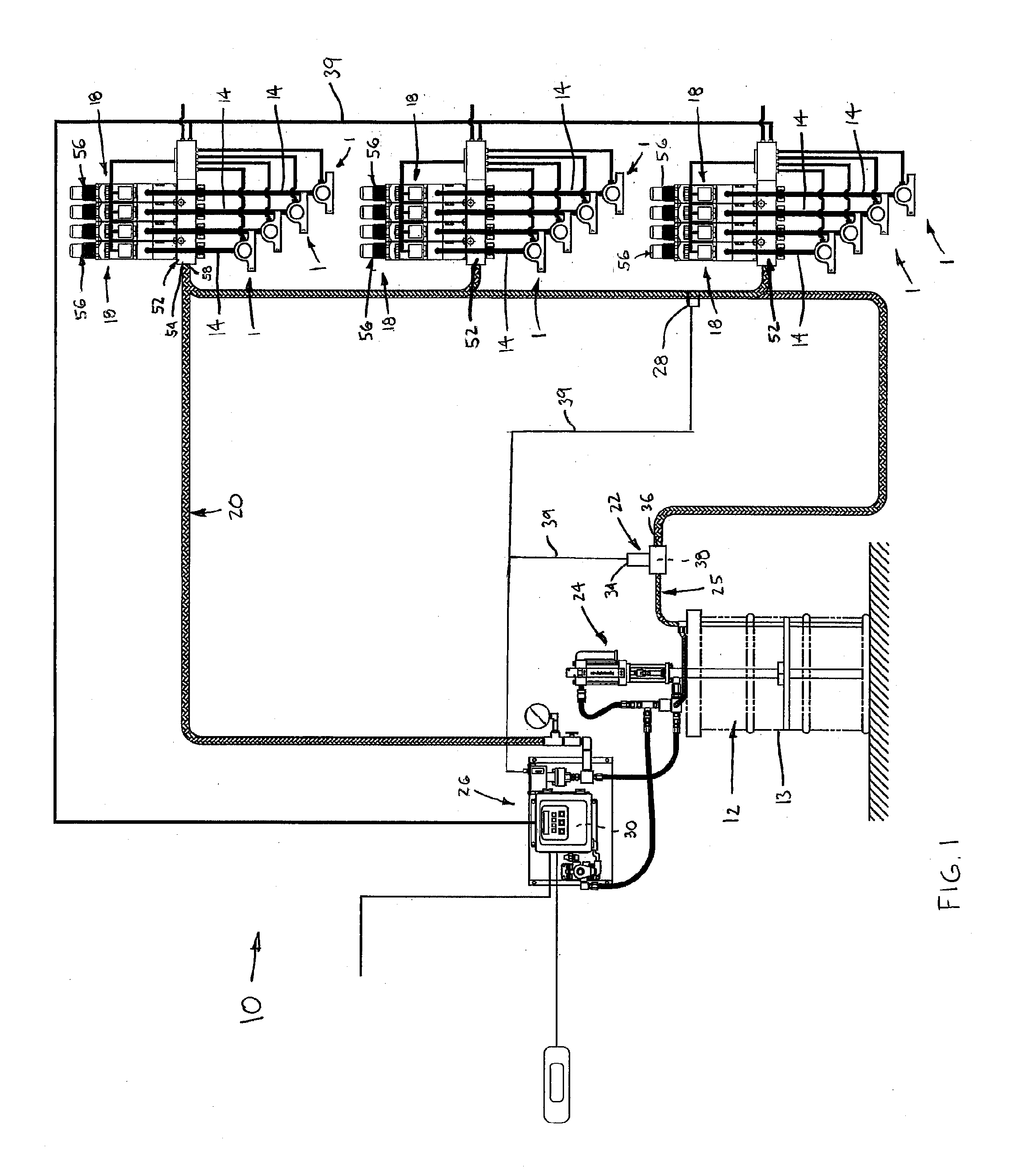
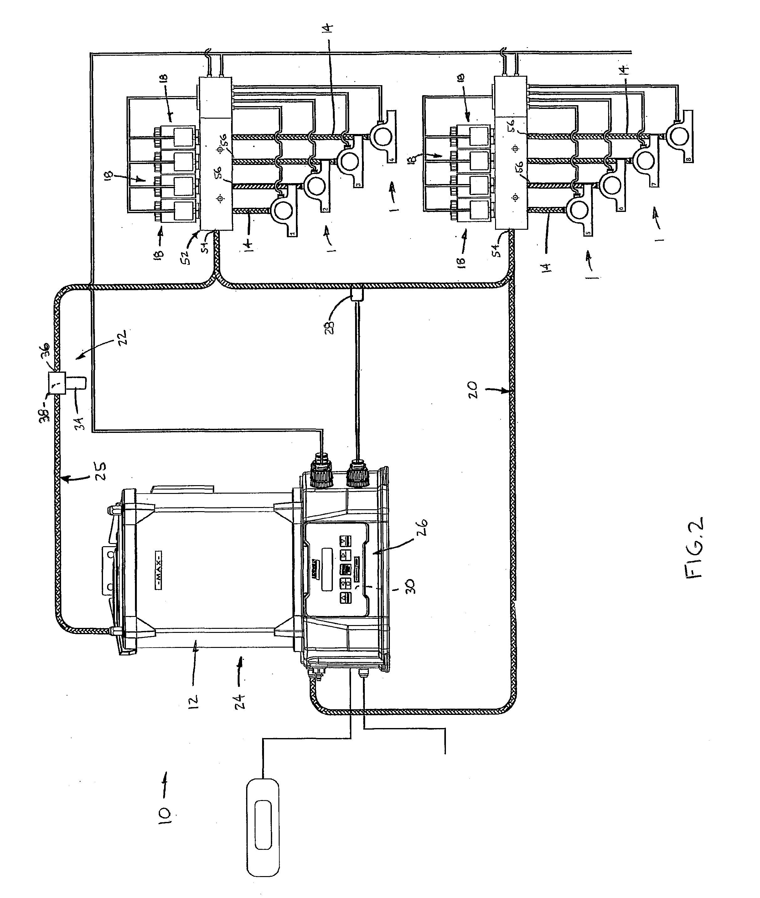
[0014]Referring now to the drawings in detail, wherein like numbers are used to indicate like elements throughout, there is shown in FIGS. 1-7 a lubrication system 10 for lubricating at least one movable machine component 1, such as a bearing, a gear, etc. The lubrication system 10 basically comprises a lubricant reservoir 12, at least one and preferably a plurality of dispenser lines 14, a dispenser valve 18 associated with each dispenser line 14, a supply line 20, a return valve 22, a pump 24 and a control 26. The reservoir 12 includes a tank 13 or other vessel for holding lubricant, the tank 13 being either an integral part of the pump 24, as shown in FIG. 2, or a separate component fluidly connected with the pump 24, as depicted in FIG. 1. Each dispenser line 14 has an outlet 16 for dispensing lubricant on or within a separate machine component 1 and the associated dispenser valve 18 selectively permits and prevents lubricant flow through the dispenser line 14. The supply line 2...
PUM
 Abstract
Description
Claims
Application Information