Mould for monocrystalline casting

Active Publication Date: 2017-02-16
SN DETUDE & DE CONSTR DE MOTEURS DAVIATION S N E C M A
View PDF2 Cites 1 Cited by
  • Summary
  • Abstract
  • Description
  • Claims
  • Application Information

AI Technical Summary

Benefits of technology

The present invention proposes a way to make parts with large lateral projections more efficiently by using a special mold. This mold prevents the metal material from solidifying in the horizontal projection, making it easier to separate the metal branch from the rest of the raw casting. This improves the process of molding parts with complex shapes, and makes them easier to treat afterward.

Problems solved by technology

An awkward shape in the mold cavity can constitute an obstacle to such directional solidification.
Such a sudden change of direction can give rise to defects, and in particular to unwanted grains, in the proximity of the projection.
Nevertheless, a drawback of such a grain duct is that it makes the mold more difficult to knock out, and above all the metal branches that result from the solidification of the metal material in the grain duct subsequently need to be removed from the raw casting, thereby adding finishing-off steps that are complicated and expensive.

Method used


Image

  • Mould for monocrystalline casting
  • Mould for monocrystalline casting
  • Mould for monocrystalline casting

Examples


Embodiment Construction

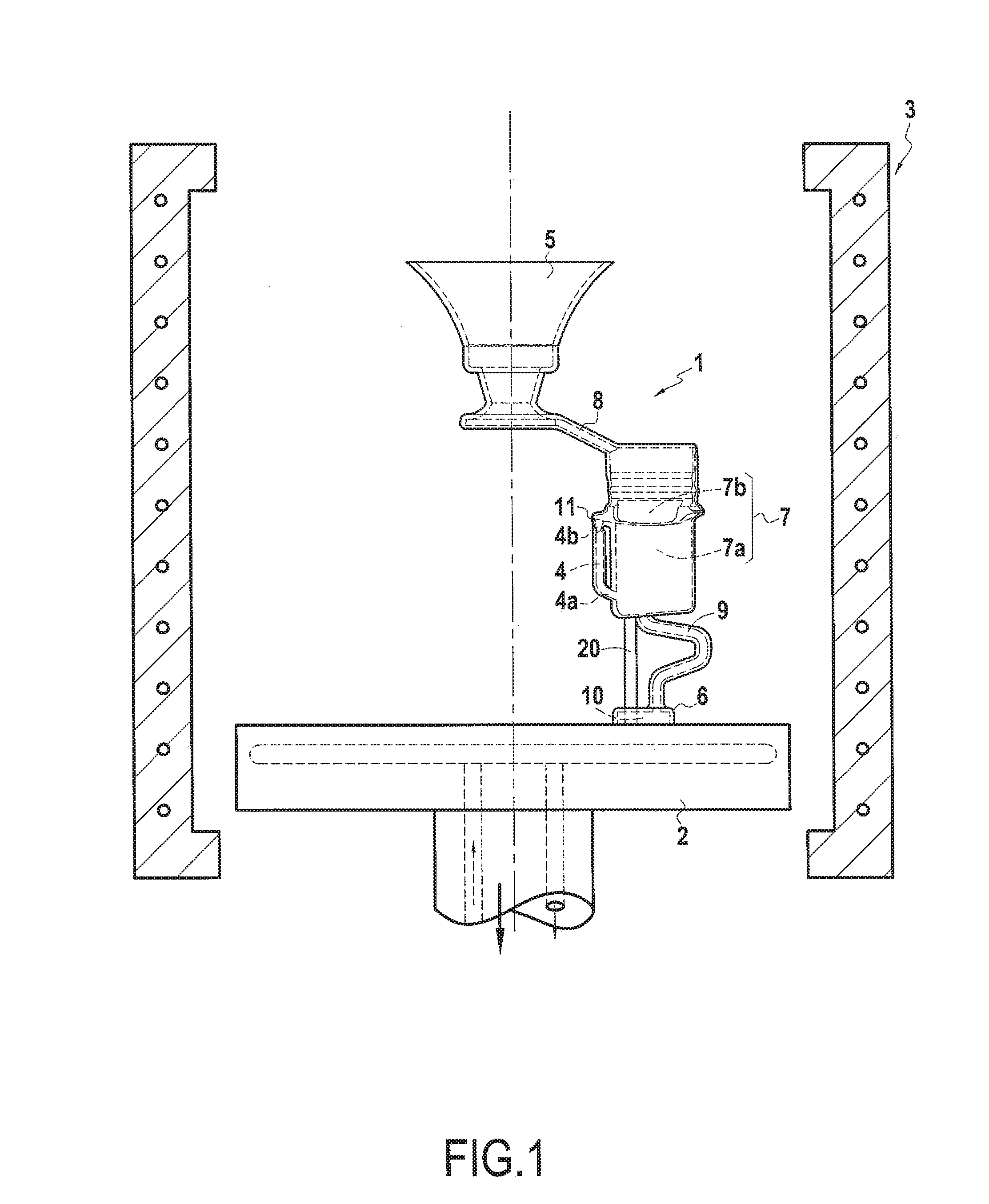
[0025]FIG. 1 shows how progressive cooling of molten metal for obtaining directional solidification can typically be performed in a casting method.

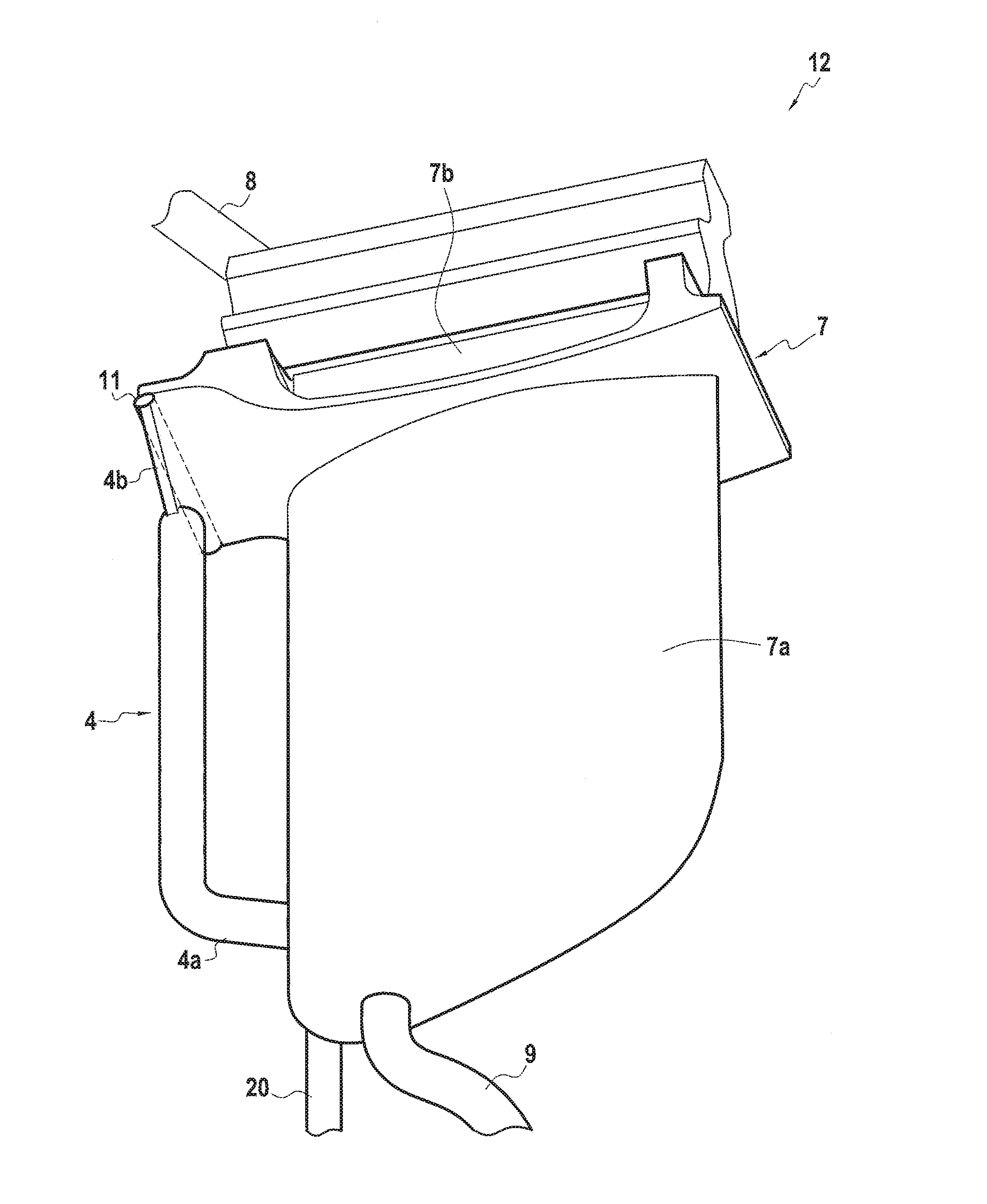
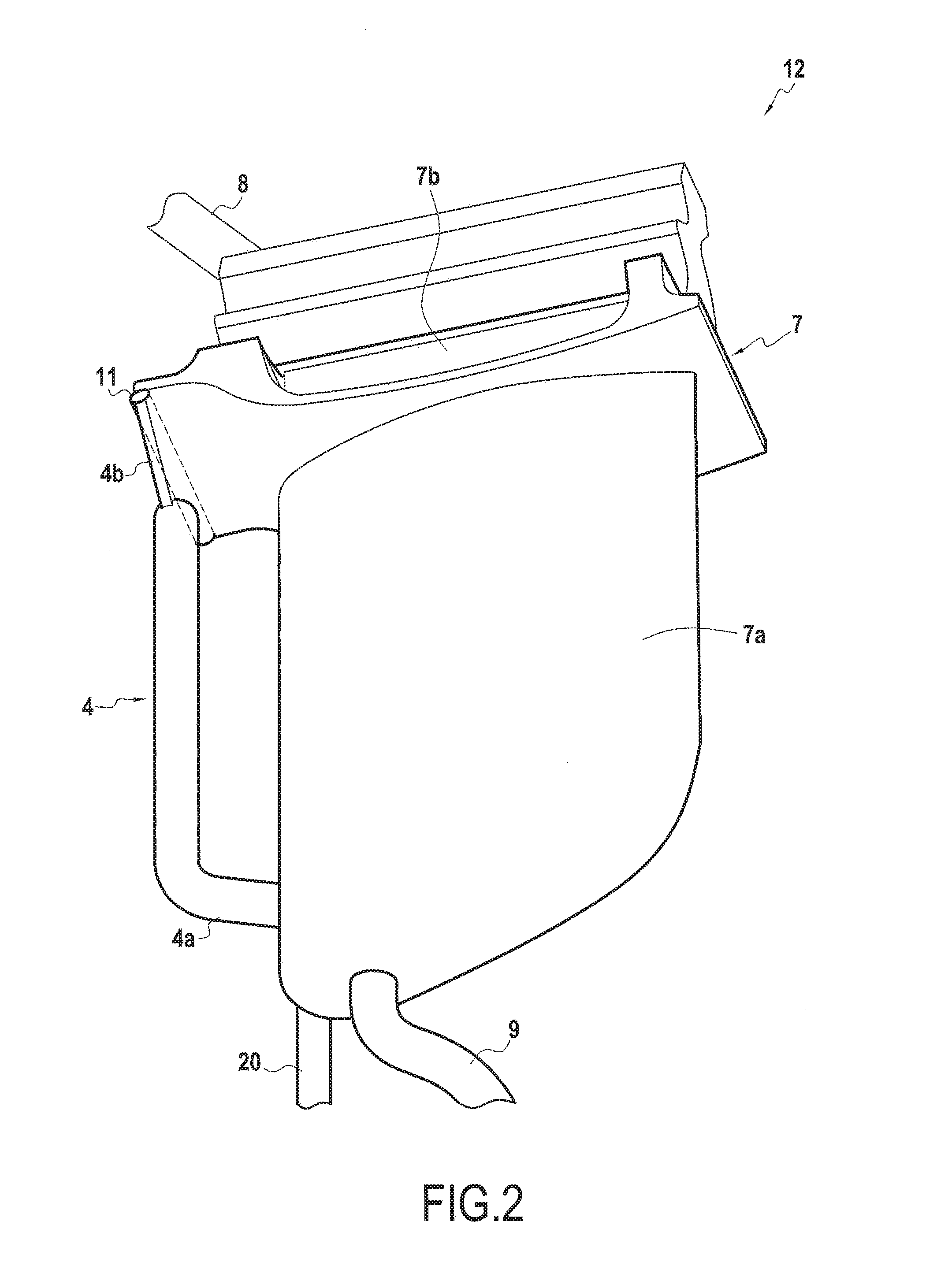
[0026]The mold 1 used in this method comprises a pouring bush 5 and a base 6. While the mold 1 is being extracted from the heater chamber 3, the base 6 is directly in contact with a soleplate 2. The mold 1 also has a molding cavity 7. It is also possible to arrange a plurality of molding cavities in a cluster in the same mold. The molding cavity 7 is connected to the pouring bush 5 by a feed channel 8 into which molten metal penetrates while it is being poured. The molding cavity 7 is also generally connected at the bottom via a baffle-shaped selector channel 9 to a smaller starter cavity 10 in the base 6. In the embodiment shown, the molding cavity 7 has a first volume 7a and a second volume 7b situated directly above the first volume 7a, and in communication therewith, while being substantially wider in a horizontal plane, so as to pres...


PUM

PropertyMeasurementUnit
Temperatureaaaaaaaaaa
Volumeaaaaaaaaaa
Shapeaaaaaaaaaa

Abstract

The invention relates to the field of monocrystalline casting, and more specifically to a mold (1) for monocrystalline casting, and also to fabricating and using the mold. In particular, the mold (1) presents a mold cavity (7) comprising a first volume (7a), a second volume (7b) and a grain duct (4). The second volume (7b) is situated on the first volume (7a), being in communication therewith, and includes at least one horizontal projection relative to the first volume (7a). The grain duct (4) has a bottom end (4a) connected to the first volume (7a) and a top end (7b) adjacent to said horizontal projection of the second volume (7b). The mold (1) also has a separator member (11) interposed between the second volume (7b) of the mold cavity (7) and the top end (4b) of the grain duct (4).

Description

BACKGROUND OF THE INVENTION[0001]The present invention relates to the field of casting, and more particularly to a model for lost-pattern casting, and also to methods of fabricating shell molds and of casting using such a model.[0002]In the description below, the terms “top”, “bottom”, “horizontal”, and “vertical” are defined relative to the normal orientation of such a mold while metal is being cast into it.[0003]So-called “lost-wax” or “lost-pattern” casting methods have been known since antiquity. They are particularly suitable for producing metal parts of complex shape. Thus, lost-pattern casting is used in particular for producing turbomachine blades.[0004]In lost-pattern casting, the first step is normally to make a model out of a material having a melting temperature that is comparatively low, e.g. a wax or a resin. The model is itself coated in a refractory material in order to from a mold, in particular a mold of the shell mold type. After the model of the material has been...

Claims


Application Information

Patent Timeline
IPC IPC(8): B22C9/04B22C9/22B22D29/00B22D25/02B22D27/04B22C7/02B22D18/06
CPCB22C9/043B22C7/02B22C9/22B22D29/00B22D25/02B22D27/045B22D18/06
Inventor FARGEAS, SERGECOYEZ, DOMINIQUE
Owner SN DETUDE & DE CONSTR DE MOTEURS DAVIATION S N E C M A
Why Eureka
Try Eureka