

Seat air conditioning device for vehicle
- Summary
- Abstract
- Description
- Claims
- Application Information
AI Technical Summary
Benefits of technology
Problems solved by technology
Method used
Image

Examples
first embodiment
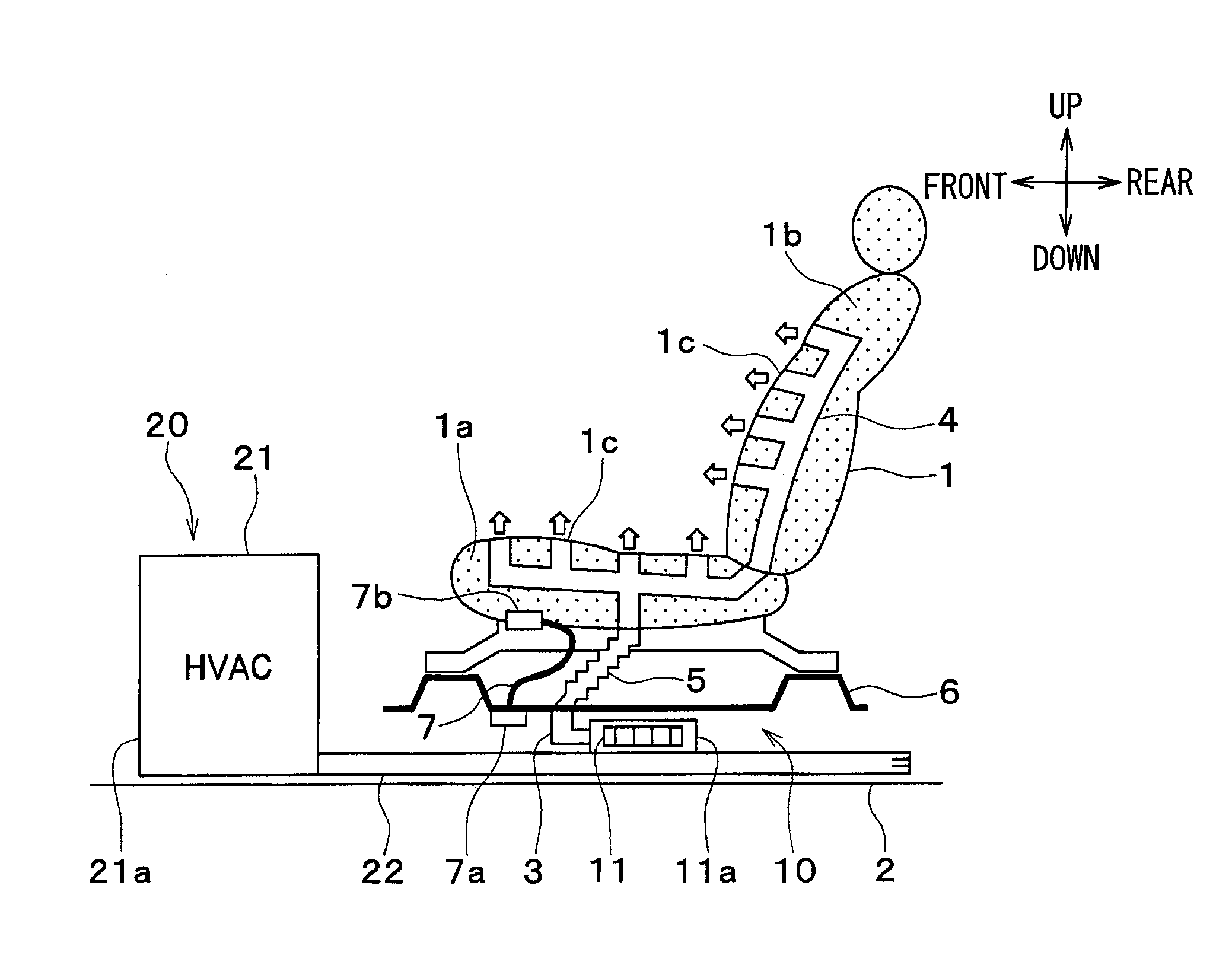
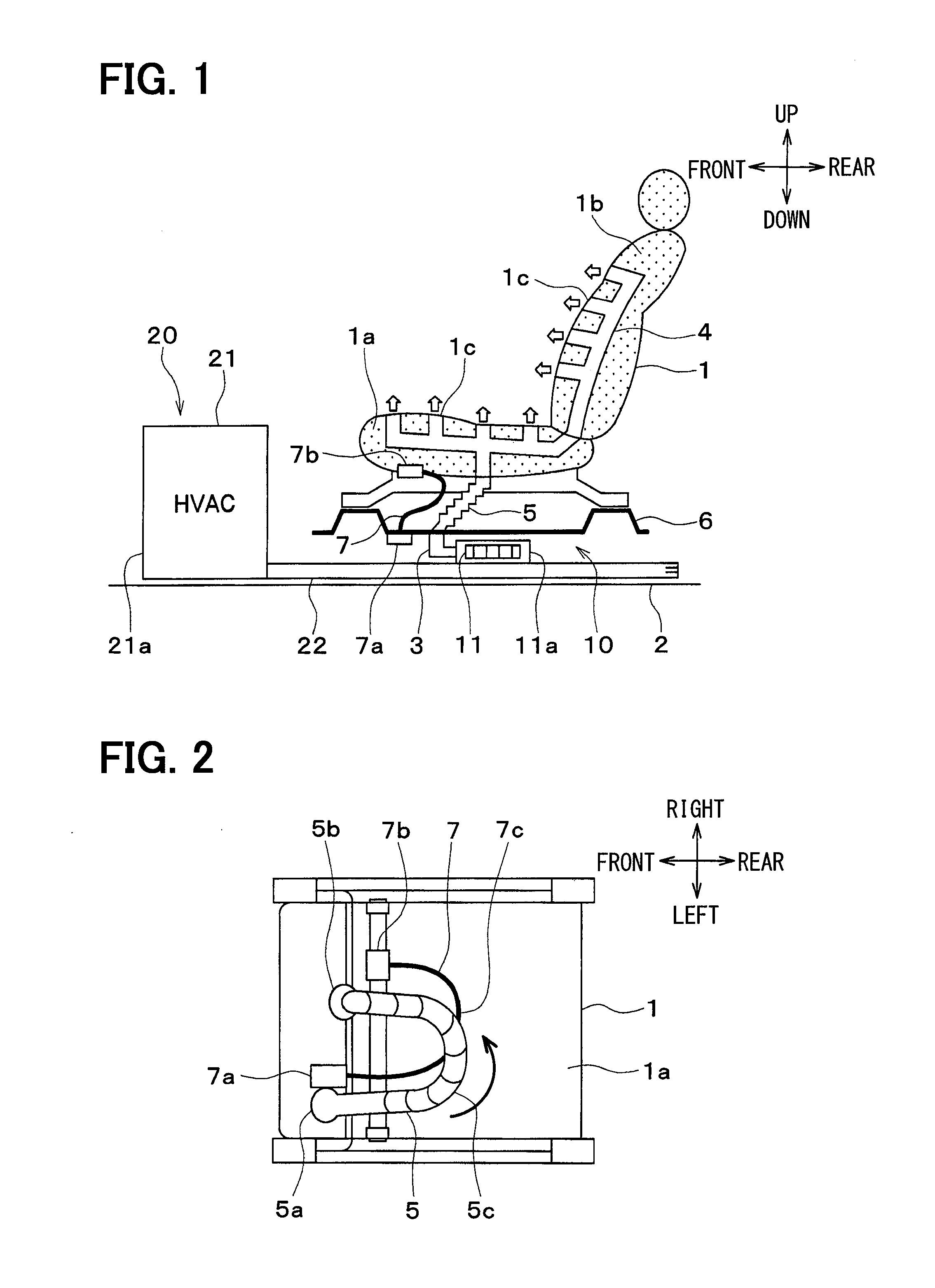
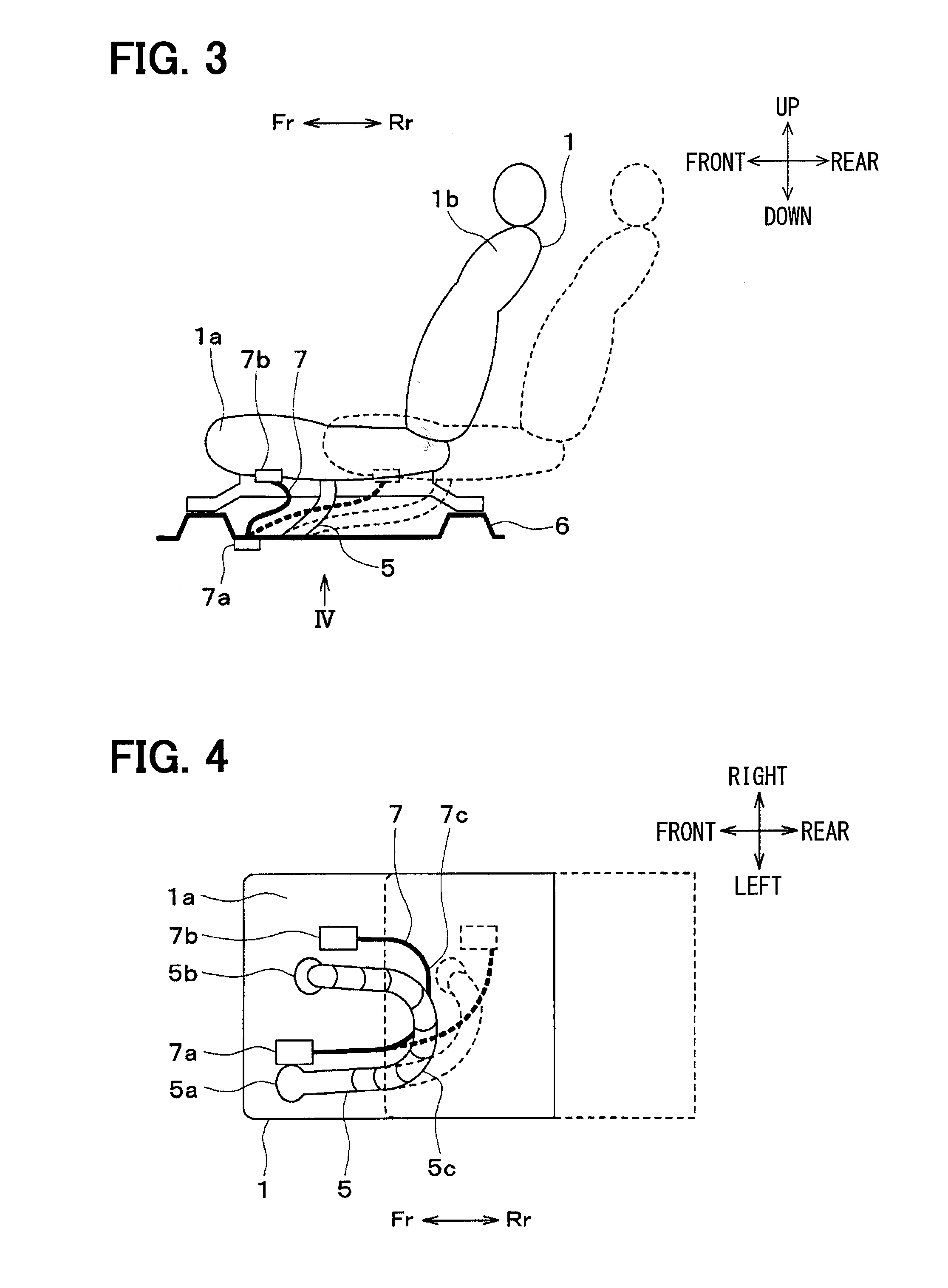
[0030]The first embodiment will be described with reference to FIGS. 1 to 4. In the present embodiment, a seat air conditioning device is applied to a front seat (such as a driver's seat or a passenger seat) for a vehicle. Up, down, front, and rear arrows in FIGS. 1 and 3 show upward, downward, forward, and rearward directions with respect to the vehicle. Front, rear, left, and right arrows in FIGS. 2 and 4 show forward, rearward, leftward, and rightward directions with respect to the vehicle.
[0031]The seat air conditioning device 10 is configured to blow out cold air, supplied from an interior air conditioning unit 21 of an air conditioner 20 for the vehicle that air-conditions a space in a vehicle compartment, from a surface of a front seat 1 (hereinafter simply referred to as seat 1).
[0032]The seat air conditioning device 10 includes a floor-side duct 3 disposed near a floor (vehicle floor face) 2 of a vehicle body member forming the space in the vehicle compartment and a seat-si...
second embodiment
[0058]The second embodiment will be described based on FIGS. 5 and 6. The present second embodiment is different in structures of a connecting duct 5 and a vehicle harness 7 from the above-described first embodiment. FIGS. 5 and 6 show a seat face 1a of a seat 1 seen from below a vehicle.
[0059]As shown in FIGS. 5 and 6, the connecting duct 5 is disposed at such a position as not to overlap the vehicle harness 7 in a vertical direction of the vehicle. The connecting duct 5 and the vehicle harness 7 are disposed in the same plane. Specifically, a substantially U-shaped inner peripheral face of the connecting duct 5 (the face close to a front side of the vehicle) is disposed to face a substantially U-shaped outer peripheral of the vehicle harness 7 (the face close to a rear side of the vehicle).
[0060]According to the present embodiment, as shown in FIG. 6, when a front-rear position of the seat 1 is adjusted, the connecting duct 5 and the vehicle harness 7 can be moved while kept paral...
third embodiment
[0062]The third embodiment will be described with reference to FIGS. 7 and 8. As shown in FIGS. 7 and 8, a connecting duct 5 and a vehicle harness 7 are bound by a binding member 8. The binding member 8 of the present embodiment is formed by a clip member integrally formed by a retaining portion 8a that retains the connecting duct 5, and a retaining portion 8b that retains the vehicle harness 7.
[0063]According to the present embodiment, when a front-rear position of a seat 1 is adjusted, the connecting duct 5 and the vehicle harness 7 can be moved smoothly while bound together. Therefore, it is possible to obtain enhanced effect in suppressing interference between the connecting duct 5 and the vehicle harness 7 and enhanced effect in suppressing entanglement of the connecting duct 5 to the vehicle harness 7. As a result, it is possible to further improve ease of mounting. Moreover, unintended deformation of the connecting duct 5 and the vehicle harness 7 can be suppressed and the co...
PUM
 Abstract
Description
Claims
Application Information