Device and Method for Magnetically Controlled Dry Gas Seal

a magnetic control and dry gas seal technology, applied in the direction of engine seals, mechanical equipment, engine components, etc., can solve the problems of increasing pressure requirements, failures of dry gas seals, and consuming time and money

Active Publication Date: 2017-02-16
EXXONMOBIL UPSTREAM RES CO
View PDF1 Cites 22 Cited by
  • Summary
  • Abstract
  • Description
  • Claims
  • Application Information

AI Technical Summary

Benefits of technology

[0009]In another aspect, a method of controlling an axial separation between a rotating ring and a stationary ring of a dry gas seal is disclosed. The dry gas seal restricts leakage of a gas or other fluid to or from a rotating device. At least one sensing device is used to sense (i) the axial separation between the rotating ring and the stationary r...

Problems solved by technology

The use of dry gas seals on compressors in the oil & gas industry is pervasive; yet despite decades of experience and technology advancements the failures of dry gas seals continue to consume time and money.
Some failures can certainly be attributed to increasing pressure requirements, more difficult gas compositions, and functional requirements.
The greatest proportion of those failures are caused by operational difficulties of the buffer gas supply system which contaminate buffer gas with liquid, water, solids, reverse pressurization, etc.
These contaminants interrupt the film between the seal faces and cause the faces to contact, which can induce rapid heating ...

Method used


Image

  • Device and Method for Magnetically Controlled Dry Gas Seal
  • Device and Method for Magnetically Controlled Dry Gas Seal
  • Device and Method for Magnetically Controlled Dry Gas Seal

Examples


Embodiment Construction

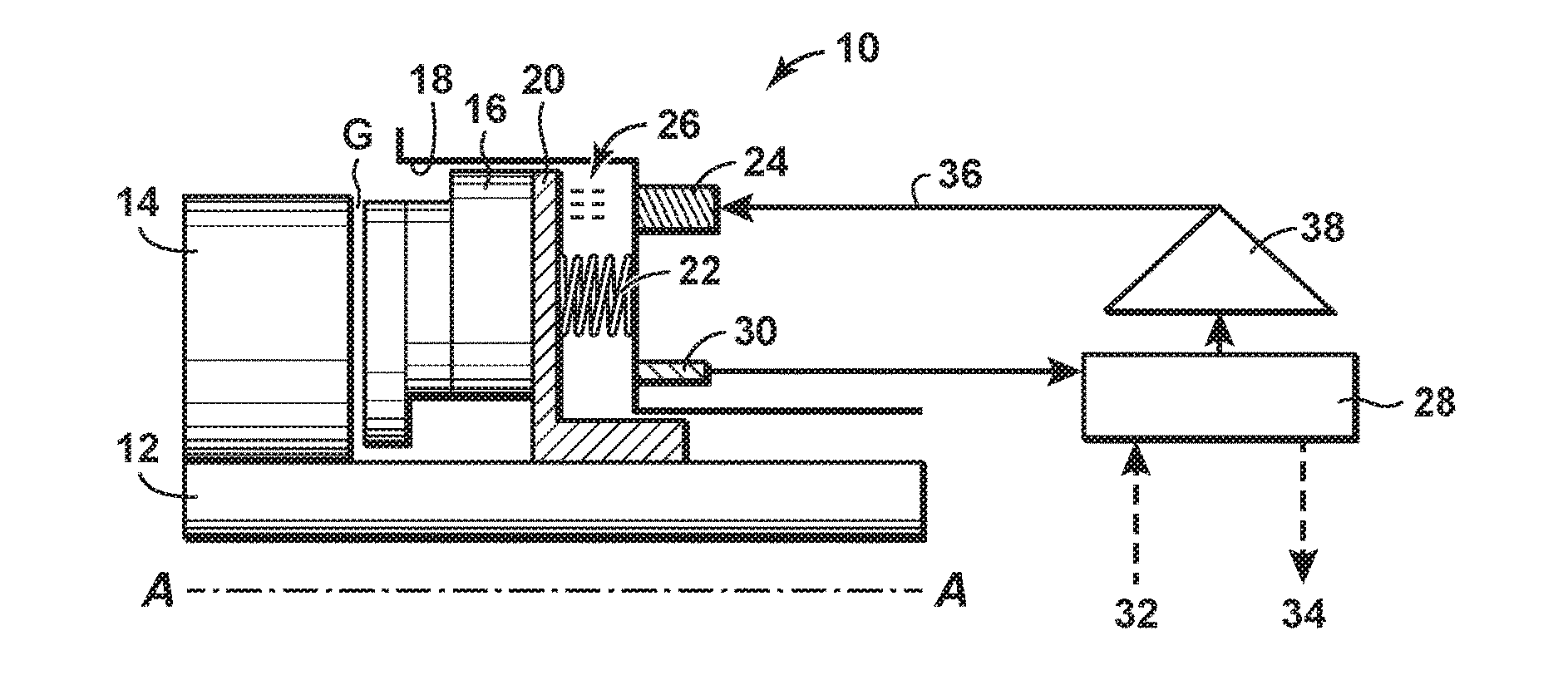
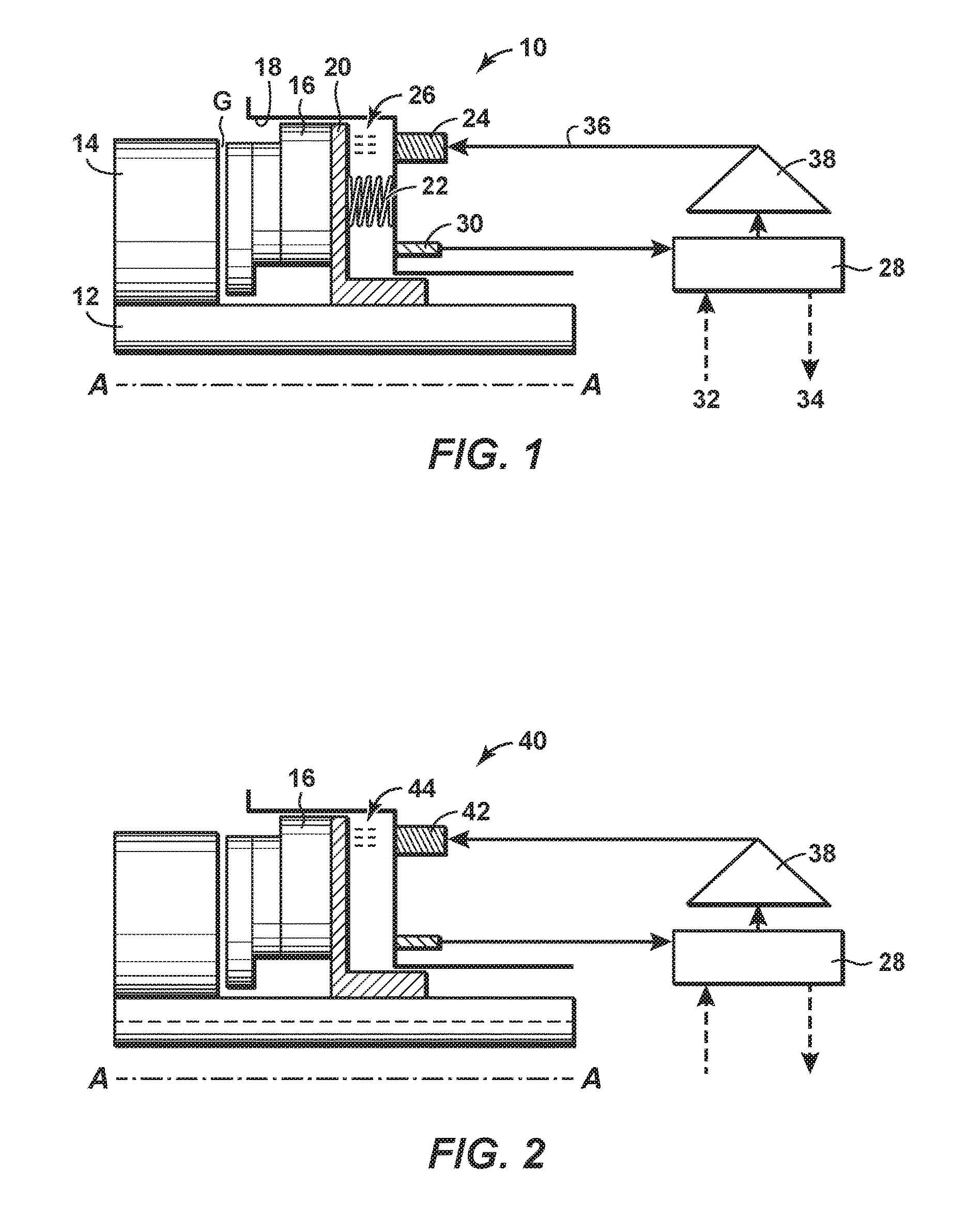
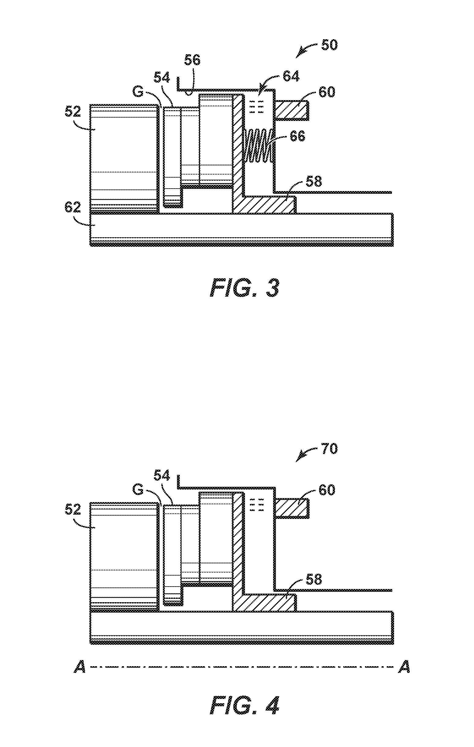
[0017]Various specific embodiments and versions of the present invention will now be described, including preferred embodiments and definitions that are adopted herein. While the following detailed description gives specific preferred embodiments, those skilled in the art will appreciate that these embodiments are exemplary only, and that the present invention can be practiced in other ways. Any reference to the “invention” may refer to one or more, but not necessarily all, of the embodiments defined by the claims. The use of headings is for purposes of convenience only and does not limit the scope of the present invention. For purposes of clarity and brevity, similar reference numbers in the several Figures represent similar items, steps, or structures and may not be described in detail in every Figure.

[0018]To promote an understanding of the principles of the disclosure, reference will now be made to the features illustrated in the drawings and specific language will be used to de...


PUM


Abstract

A method to control an axial separation between a rotating ring and a stationary ring of a dry gas seal. The dry gas seal restricts leakage of a gas or other fluid to or from a rotating device. At least one property of the gas or other fluid is sensed. At least one of the axial separation between the rotating ring and the stationary ring, and a time rate of change of the axial separation, is sensed. A stiffness of a film between the rotating ring and the stationary ring is estimated. A field strength of at least one magnetic device is adjusted based on at least two of the sensed axial separation, the sensed time rate of change of the separation, and the estimated film stiffness. The axial separation between the rotating ring and the stationary ring is adjusted.

Description

CROSS-REFERENCE TO RELATED APPLICATIONS[0001]This patent application is related to U.S. Provisional Patent Application No. 62 / 203,074, titled “DEVICE AND METHOD FOR MAGNETICALLY CONTROLLED DRY GAS SEAL”, and filed on Aug. 10, 2015, the disclosure of which is incorporated by reference herein in its entirety.BACKGROUNDField of Disclosure[0002]The invention relates to rotating machinery, and more specifically, to reducing the occurrence of failure of dry gas seals.Description of Related Art[0003]This section is intended to introduce various aspects of the art, which may be associated with the present disclosure. This discussion is intended to provide a framework to facilitate a better understanding of particular aspects of the present disclosure. Accordingly, it should be understood that this section should be read in this light, and not necessarily as an admission of prior art.[0004]The use of dry gas seals on compressors in the oil & gas industry is pervasive; yet despite decades of ...

Claims


Application Information

Patent Timeline
IPC IPC(8): F16J15/43
CPCF16J15/43F16J15/3444F16J15/3492
Inventor KHAIRA, NIRAN SINGHHUNTINGTON, RICHARD A.MATHEIDAS, MICHAEL T.
Owner EXXONMOBIL UPSTREAM RES CO
Why Eureka
Try Eureka