Display device

Active Publication Date: 2017-02-16
CORETRONIC
View PDF5 Cites 10 Cited by
  • Summary
  • Abstract
  • Description
  • Claims
  • Application Information

AI Technical Summary

Benefits of technology

[0011]Based on the foregoing descriptions, the embodiments of the invention have at least one of the advantages below. In the display device of the invention, the frame supports the display panel and the backlight module respectively with the first supporting portion and the second supporting portion thereof, and the side surface of the frame is indeed the exterior surface of the display device. Accordingly, the display device of the invent

Problems solved by technology

In general, a display requires to be additionally configured with a back plate and a plastic frame on a main frame thereof for assembling the backlight module and the display panel, and be additionally configured with a side frame on the main frame for servi

Method used


Image

  • Display device
  • Display device
  • Display device

Examples


first embodiment

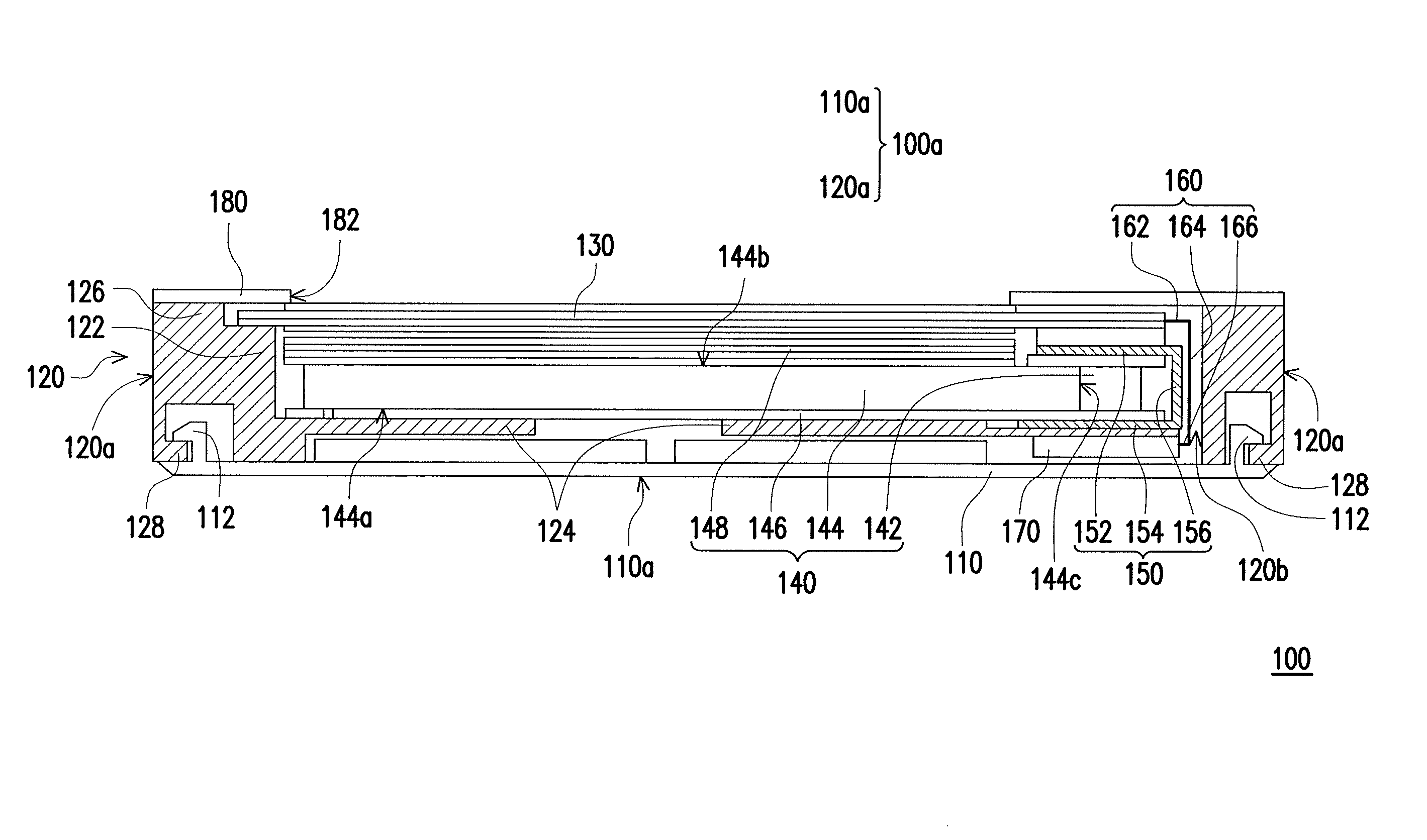
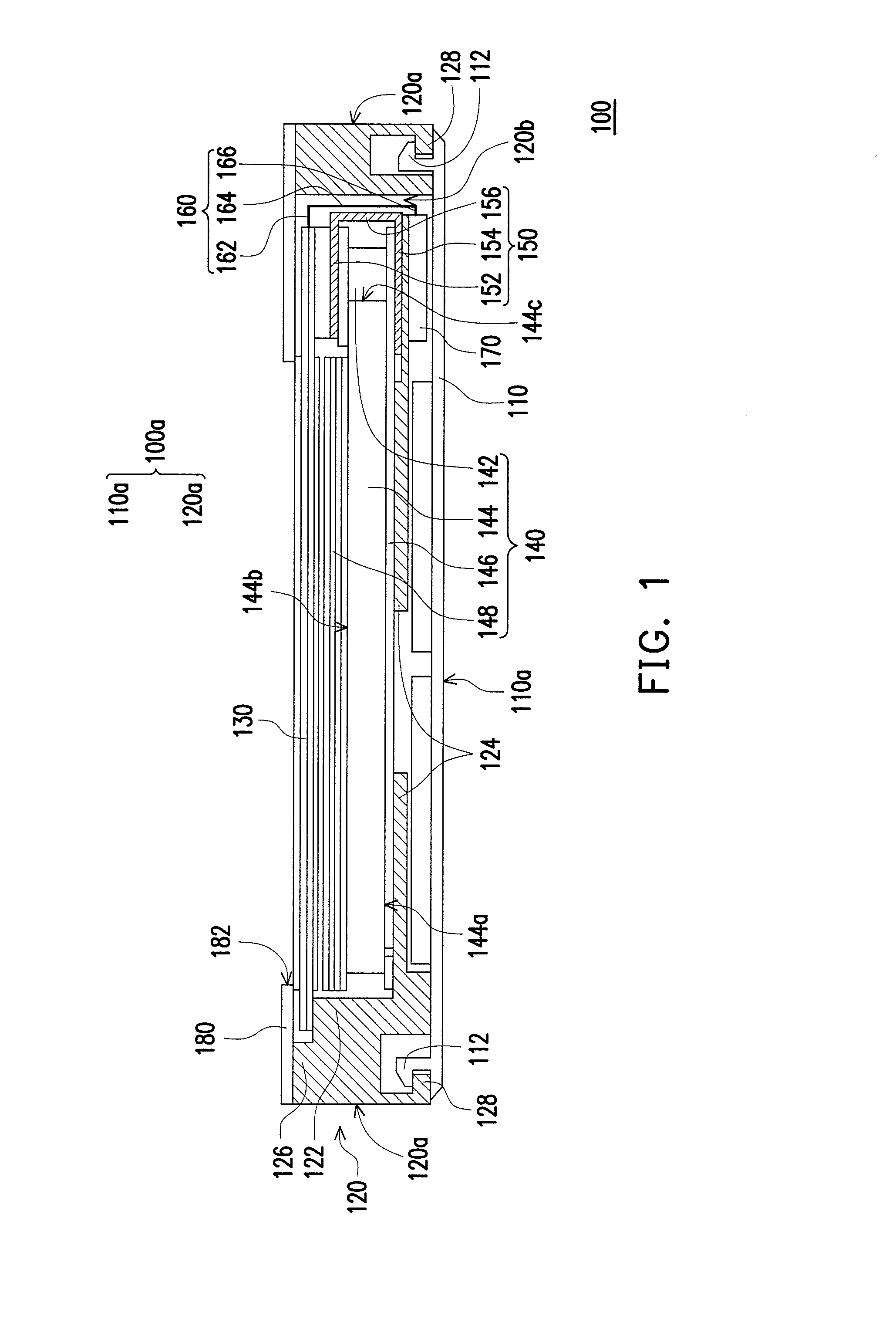
[0024]FIG. 1 is a cross-sectional diagram illustrating a display device 100 according to of the invention. Referring to FIG. 1, the display device 100 of the present embodiment has an exterior surface 100a, and the display device 100 includes a back cover 110, a frame 120, a display panel 130 and a backlight module 140. The back cover 110 has a surface 110a. The frame 120 is assembled to the back cover 110 and has a first supporting portion 122, a second supporting portion 124 and at least one side surface 120a (two are illustrated in FIG. 1). The side surfaces 120a of the frame 120 are a portion of the exterior surface of the display device 100. The side surfaces 120a of the frame 120 are adjacent to the surface 110a of the back cover 110, and the side surfaces 120a and the surface 110a are both being at least a portion of the exterior surface 100a. the display panel 130 is, for example, a liquid crystal display panel and is disposed inside the frame 120, and the first supporting p...

second embodiment

[0032]FIG. 3 is a cross-sectional diagram illustrating a display device 200 according to of the invention. In the display device 200 of FIG. 3, configurations and functions of the same elements are similar to that of FIG. 1, and thus will not be repeated. A difference between the display device 200 and the display device 100 lies in that, the front cover 280 of the display device 200 is not a front frame, such that the front cover 280 is a transparent cover and covers the display panel 230. For instance, the transparent cover may be a transparent protective plate having no touch function or a touch panel with touch function, but the invention is not limited thereto.

third embodiment

[0033]FIG. 4 is a cross-sectional diagram illustrating a display device 300 according to of the invention. In the display device 300 of FIG. 4, configurations and functions of the same elements are similar to that of FIG. 1, and thus will not be repeated. A difference between the display device 300 and the display device 100 lies in that, the cover 350 is integrally connected with the frame 320, so that the number of components in the display device 300 can further be reduced.


PUM


Abstract

A display device having an exterior surface and including a back cover, a frame, a display panel and a backlight module is provided. The frame is assembled to the back cover and has a first supporting portion and a second supporting portion. The display panel is disposed in the frame, wherein the first supporting portion supports the display panel. The backlight module is disposed in the frame and located between the back cover and the display panel, wherein the second supporting portion supports the backlight module. The frame has a side surface, and the side surface is a portion of the exterior surface.

Description

CROSS-REFERENCE TO RELATED APPLICATION[0001]This application claims the priority benefit of Taiwan application serial no. 104125894, filed on Aug. 10, 2015. The entirety of the above-mentioned patent application is hereby incorporated by reference herein and made a part of this specification.BACKGROUND[0002]1. Field of the Invention[0003]The invention generally relates to a display device, and more particularly, to a display device with a backlight module.[0004]2. Description of Related Art[0005]With the increasingly developments of the semiconductor industry and related electronic industries, smart phones, notebooks, tablet PC, and digital display devices are all developing toward a more convenient, versatile, and aesthetically appearance direction. When using these products, a display screen is an indispensable interface, wherein, liquid crystal displays (LCD) have become the main stream for display screens. Due to the reason that the LCD panel does not emit light inherently, a ba...

Claims


Application Information

Patent Timeline
IPC IPC(8): F21V8/00G02F1/1345G02F1/1333
CPCG02B6/0088G02B6/0083G02B6/0091G02F2001/13332G02F1/13452G02F2001/133314G02F1/133308G02F1/1336G02F1/133317
Inventor HSU, SUNG-CHUNHSU, JENG-BIN
Owner CORETRONIC
Why Eureka
Try Eureka