Image reading device

a technology of image reading and light source, applied in the field of image reading devices, can solve the problems of density unevenness in images, uneven distribution of light amount in light sources, and difference in light converging performance, and achieve the effect of reducing density unevenness

Active Publication Date: 2017-02-23
PANASONIC INTELLECTUAL PROPERTY MANAGEMENT CO LTD
View PDF14 Cites 9 Cited by
  • Summary
  • Abstract
  • Description
  • Claims
  • Application Information

AI Technical Summary

Benefits of technology

[0011]With this configuration, the image reading device performs the shading correction using the correction data in the respective positions in the sub-scanning direction. This configuration can provide the image reading device that can reduce the density unevenness on the image in the main scanning direction and the sub-scanning direction caused by the interference between the image signals from the plurality of sensors.

Problems solved by technology

Such a distortion is caused by unevenness in light receiving elements of a sensor module such as a CCD (Charge Coupled Device) and a CIS (Contact Image Sensor), the difference in light converging performance between a central part and a peripheral part of a lens, and unevenness in a light amount distribution of a light source.
However, density unevenness is generated in an image in some cases in a configuration in which a plurality of sensors is disposed in a main scanning direction and in which the image signals constitute an image signal on a line extending in the main scanning direction.
The density unevenness is caused by the interference between the outputs from the plurality of sensors.
Such a density difference cannot be corrected sufficiently only by the above-described shading correction.
However, when the density level becomes a bit lower than black, the output level of sensor 207 increases, and the interference noise increases accordingly.
As a result, the shading correction cannot be appropriately performed.
At this time, since the interference noise included in the output level of white is great, an influence due to the fluctuation in the interference noise becomes great.
However, since the density level of the first black data is high, the output level itself is low, and the contained interference noise is also small.
That is, although the first black data is the data of black at a high density level, the interference noise is not appropriately included.

Method used


Image

  • Image reading device
  • Image reading device
  • Image reading device

Examples


first exemplary embodiment

[1. Configuration]

[1-1. Multifunction Peripheral]

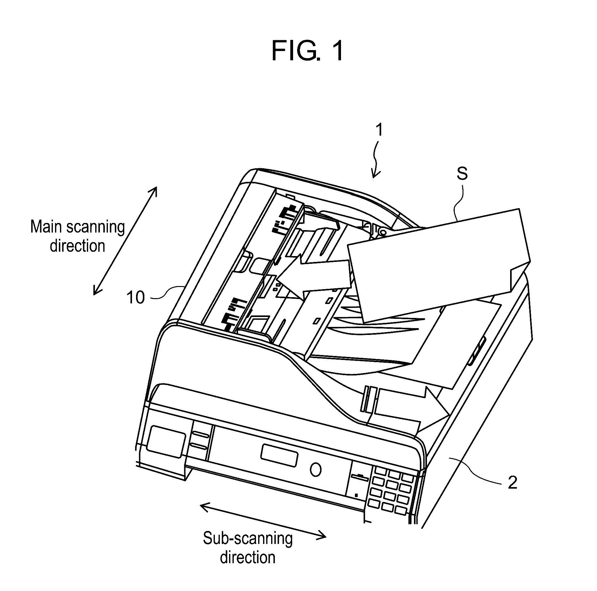
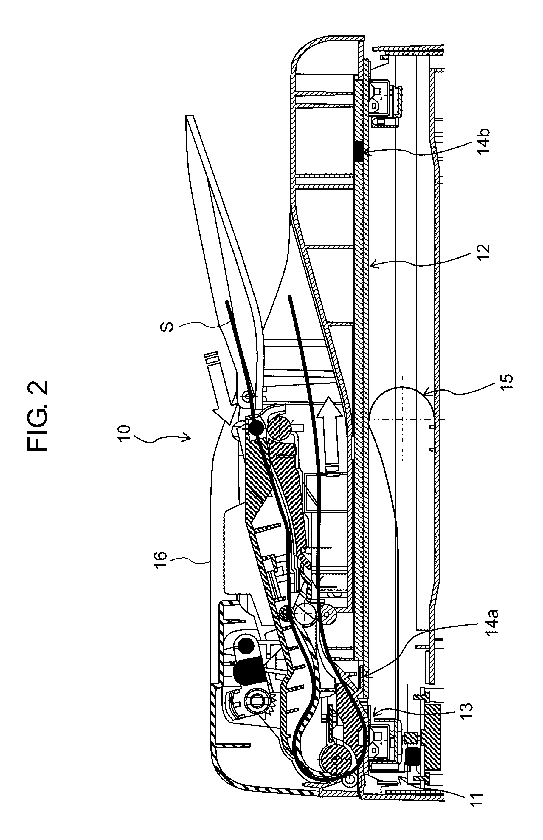
[0037]A hardware configuration of multifunction peripheral 1 including image reading device 10 in a first exemplary embodiment is described with reference to FIGS. 1 and 2. FIG. 1 is a perspective view of a multifunction peripheral of the image reading device in the first exemplary embodiment. FIG. 2 is a sectional view of the multifunction peripheral in the first exemplary embodiment.

[0038]Multifunction peripheral 1 includes main unit 2 and image reading device 10 mounted on an upper part of main unit 2. Multifunction peripheral 1 has a scan function performed by image reading device 10, and in addition, other functions (for example, a print function, a copy function, a facsimile transmission / reception function, and the like). Main unit 2 has a configuration according to a function of multifunction peripheral 1.

[0039]Image reading device 10 is an FB (Flat Bed) type image scanner as shown in FIGS. 1 and 2. Image reading device 10 has ...

second exemplary embodiment

[0147]A second exemplary embodiment will describe a case where reference sheet 3 is used for acquiring third black data and second white data. That is, in the second exemplary embodiment, reference sheet 3 is a second reference member.

[0148]Since parts other than the part of the configuration described here are similar to the first exemplary embodiment, description thereof will be omitted.

[2-1. Reference Plate]

[0149]In the second exemplary embodiment, only first reference plate 14a is disposed in a first position, and second reference plate 14b is not disposed. First reference plate 14a is similar in a configuration to the first exemplary embodiment.

[2-2. Acquisition of Data]

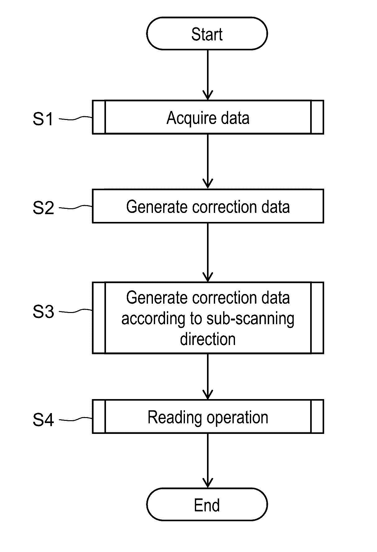
[0150]Acquisition of image data for generating correction data of image reading device 10 in the second exemplary embodiment will be described. FIG. 15 is a flowchart of acquisition of image data in image reading device 10.

[0151]In the second exemplary embodiment, after a user places reference sheets on FB glass...


PUM


Abstract

An image reading device has an image processor that generates correction data to be used for shading correction and performs the shading correction using the correction data. The image processor generates intermediate data with a predetermined density level, generates intermediate data in different positions in the sub-scanning direction based on image signals of a first reference plate and a second reference plate disposed in the different positions, generates first and second black correction data based on the respective intermediate data, generates black correction data according to the sub-scanning direction based on both the black correction data, and performs the shading correction using the black correction data in the respective positions in the sub-scanning direction.

Description

BACKGROUND[0001]1. Technical Field[0002]The present disclosure relates to an image reading device that reads an image of an object.[0003]2. Description of the Related Art[0004]Unexamined Japanese Patent Publication No. 2008-060975 discloses an image reading device including a white reference plate. The image reading device acquires white reference data from an output of a sensor when an image of the white reference plate is acquired with a light source turned on. In addition, the image reading device acquires black reference data from an output of the sensor with the light source turned off. The image reading device performs shading correction based on the thus acquired white reference data and black reference data.[0005]Further, Unexamined Japanese Patent Publication No. 1110-327322 discloses an image reading device that defines a white reference level in a sub-scanning direction as well as a main scanning direction. The image reading device corrects the white reference level in th...

Claims


Application Information

Patent Timeline
Patent Type & Authority Applications(United States)
IPC IPC(8): H04N1/401H04N1/031H04N1/028
CPCH04N1/401H04N2201/0094H04N1/031H04N1/02855H04N1/4076H04N1/00018H04N1/00013H04N1/00005H04N1/00068H04N1/00039H04N1/00034H04N1/00063H04N1/00045H04N1/00053H04N1/00082H04N1/00087H04N2201/0081H04N1/125H04N1/191H04N1/193H04N1/40006H04N1/0318H04N1/12H04N1/0311H04N1/04H04N1/40056H04N1/028H04N1/19
Inventor FUSAYASU, HIROTSUGUMATSUBARA, RYOINOKUCHI, KATSUOHIROTA, TATSUYATUTIYA, YUUICHI
Owner PANASONIC INTELLECTUAL PROPERTY MANAGEMENT CO LTD
Why Eureka
Try Eureka