
Eureka
For R&D, Eureka makes reading and utilizing patents & technical documents easy.
Eureka AIR
Designed for self-driven R&D workflows. Generate viable solutions, solve complex R&D challenges, empower your innovation with AI.

Eureka Materials
Designed for material experts only. Revolutionize your material R&D, from search, analyze, to developing new materials.

TechResearch
Generate reliable direction feasibility study reports for your R&D in just a few steps.

TechSeek
Discover and master advanced knowledge NOW. Basics, ideas, possibilities, all at once.

TechMind
As an expert in R&D Theories, TechMind can generates customized viable solutions instantly.

TechRisk
Analyze your overall solution with one click, know your potential R&D risks in advance.

TechMonitor
Get weekly tech updates, stay abreast of the latest tech innovations and key insights.
Heater
- Summary
- Abstract
- Description
- Claims
- Application Information
AI Technical Summary
Benefits of technology
Problems solved by technology
Method used
Image

Examples
first embodiment
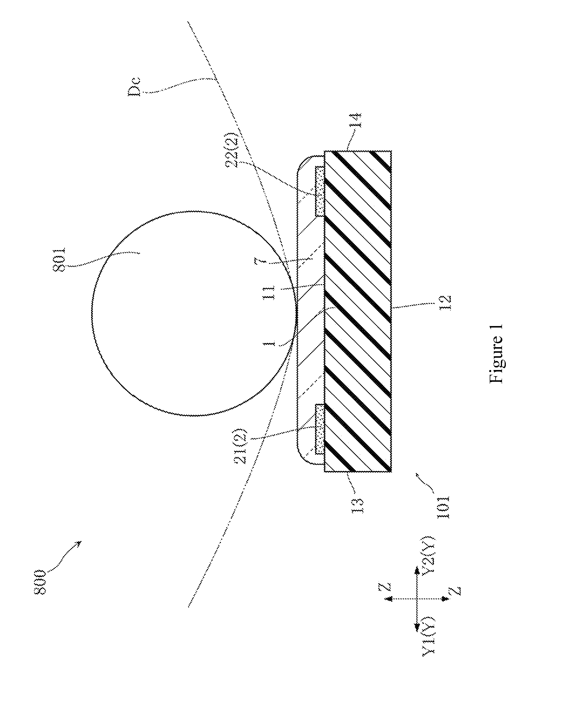
[0020]FIG. 1 is a cross-sectional view showing a device according to the present invention.
[0021]A device 800 shown in the figure is, for example, used for toner fixing in an OA (Office Automation) apparatus (for example, an electronic copier, a facsimile machine or a printer). The device 800 includes a heater 101, a platen roller 801 and a thermistor 861.
[0022]The heater 101 is opposite to the platen roller 801 for allowing the toner, which is transferred to the heated medium Dc, to be thermally fixed to the heated medium Dc.
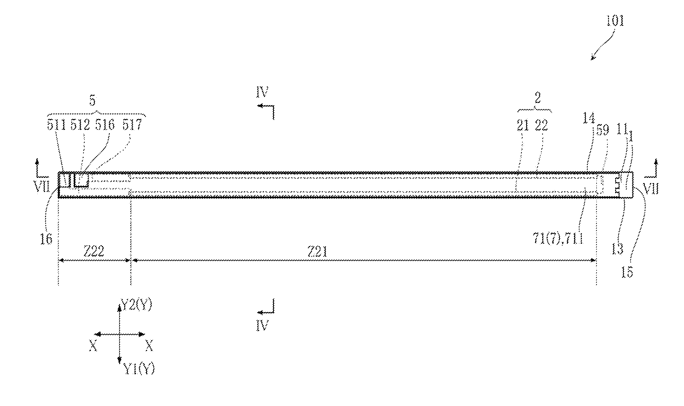
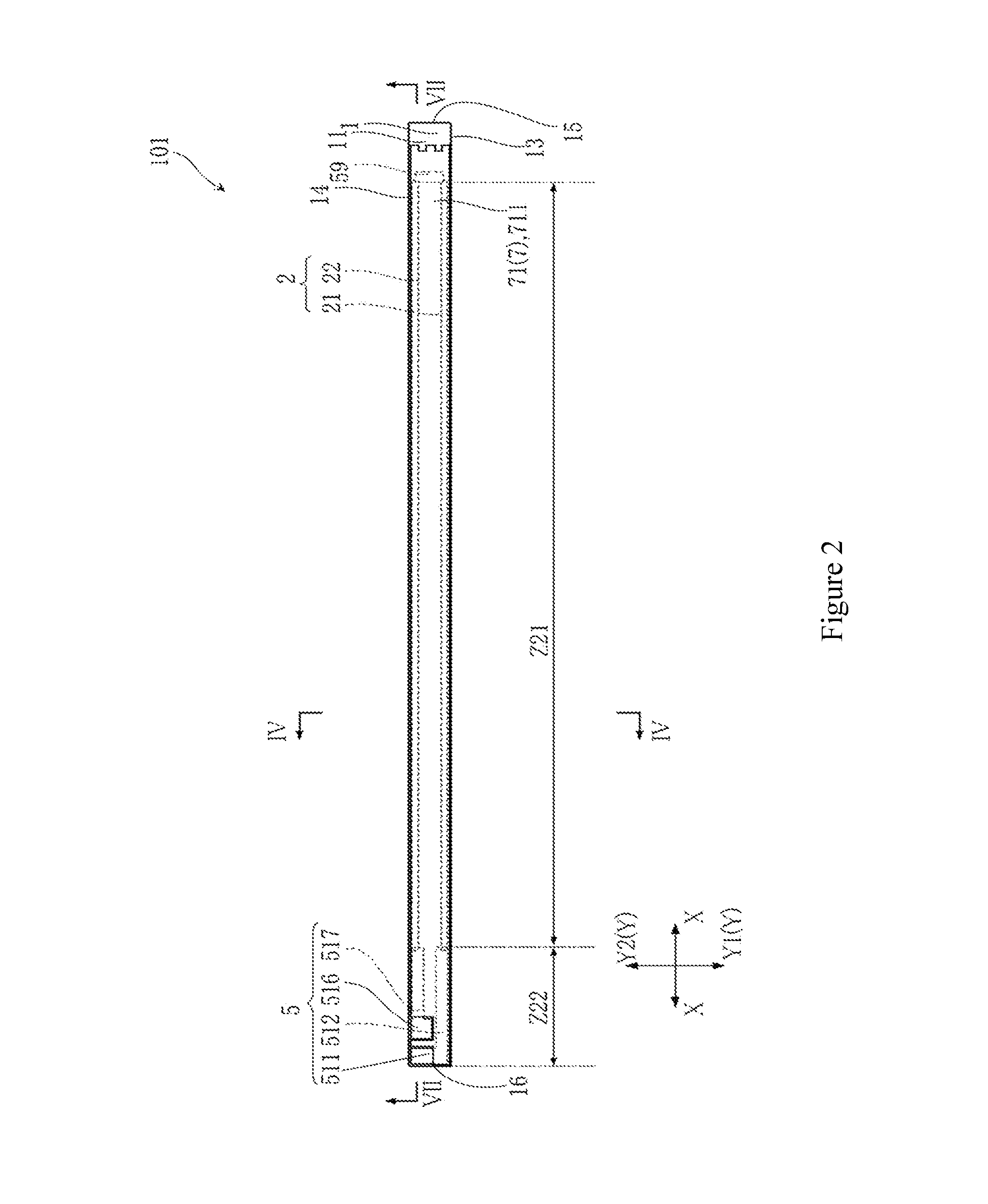
[0023]FIG. 2 is a top view showing the heater 101. FIG. 3 is a top view showing a main portion of the heater 101, in which a protection layer 7 is omitted. FIG. 4 is a cross-sectional view along the line IV-IV of FIG. 2. FIG. 5 is an enlarged cross-sectional view showing a main portion of the heater 101. FIG. 6 is an enlarged cross-sectional view showing a main portion of the heater 101. FIG. 7 is a cross-sectional view showing a main portion along the line VII...
second embodiment
[0059]FIG. 10 and FIG. 11 show a heater according to the present invention. The difference between the heater 102 of the present embodiment and the heater 101 mentioned above is that the heat resistor 2 is only includes a first elongated portion 21.
[0060]FIG. 10 is a top view showing a main portion of the heater 102, and the protection layer 7 is omitted. FIG. 11 is a cross-sectional view along line XI-XI in FIG. 10.
[0061]The first elongated portion 21 extends in a longitudinal shape along the long side direction X of the substrate 1. In the present embodiment, as shown in FIG. 11, the distances between two lateral ends in the short side direction Y of the first elongated portion 21 and two edges in the short side direction Y of the substrate 1 are respectively distance L1.
[0062]In the present embodiment, a ratio of the distance L1 to the thickness t of the substrate 1 is also more than 0 and less than 1.75, and preferably more than 0.05 and less than 1.75. The distance L1 is 0 mm˜0...
PUM
 Abstract
Description
Claims
Application Information
 - R&D Engineer
- R&D Manager
- IP Professional
- Industry Leading Data Capabilities
- Powerful AI technology
- Patent DNA Extraction
Browse by: Latest US Patents, China's latest patents, Technical Efficacy Thesaurus, Application Domain, Technology Topic, Popular Technical Reports.
© 2024 PatSnap. All rights reserved.Legal|Privacy policy|Modern Slavery Act Transparency Statement|Sitemap|About US| Contact US: help@patsnap.com