
Mold clamping apparatus

Active Publication Date: 2017-03-02
NISSEI PLASTIC IND CO LTD
View PDF2 Cites 1 Cited by
  • Summary
  • Abstract
  • Description
  • Claims
  • Application Information

AI Technical Summary

Benefits of technology

The present invention provides a mold clamping apparatus that can increase the force at the beginning of a mold opening process without increasing cost. This is achieved by using a mold thickness adjustment cylinder that generates the initial mold opening force. The apparatus can also quickly perform the mold opening process in case of a small-sized molded product, improving productivity and flexibility. The axial force in the mold thickness adjustment cylinder is set within a specific range to optimize the force and size of the cylinder. Overall, this mold clamping apparatus provides an efficient and cost-effective solution for the mold opening process.

Problems solved by technology

When the molded product is large in size, a large mold opening force is required.
To increase the mold opening force, it is considered that the cylinder diameter of the mold opening / closing actuator is increased, which, however, makes the mold opening / closing actuator expensive.
However, since the medium-diameter piston 102 and the medium-diameter oil chamber 113 need to be provided, the structure of the conventional mold clamping cylinder 100 is inevitably complicated.
Thus, in comparison to a common cylinder having a single piston and two oil passages, the conventional mold clamping cylinder 100 becomes complicated and expensive.

Method used


Image

  • Mold clamping apparatus
  • Mold clamping apparatus
  • Mold clamping apparatus

Examples


Embodiment Construction

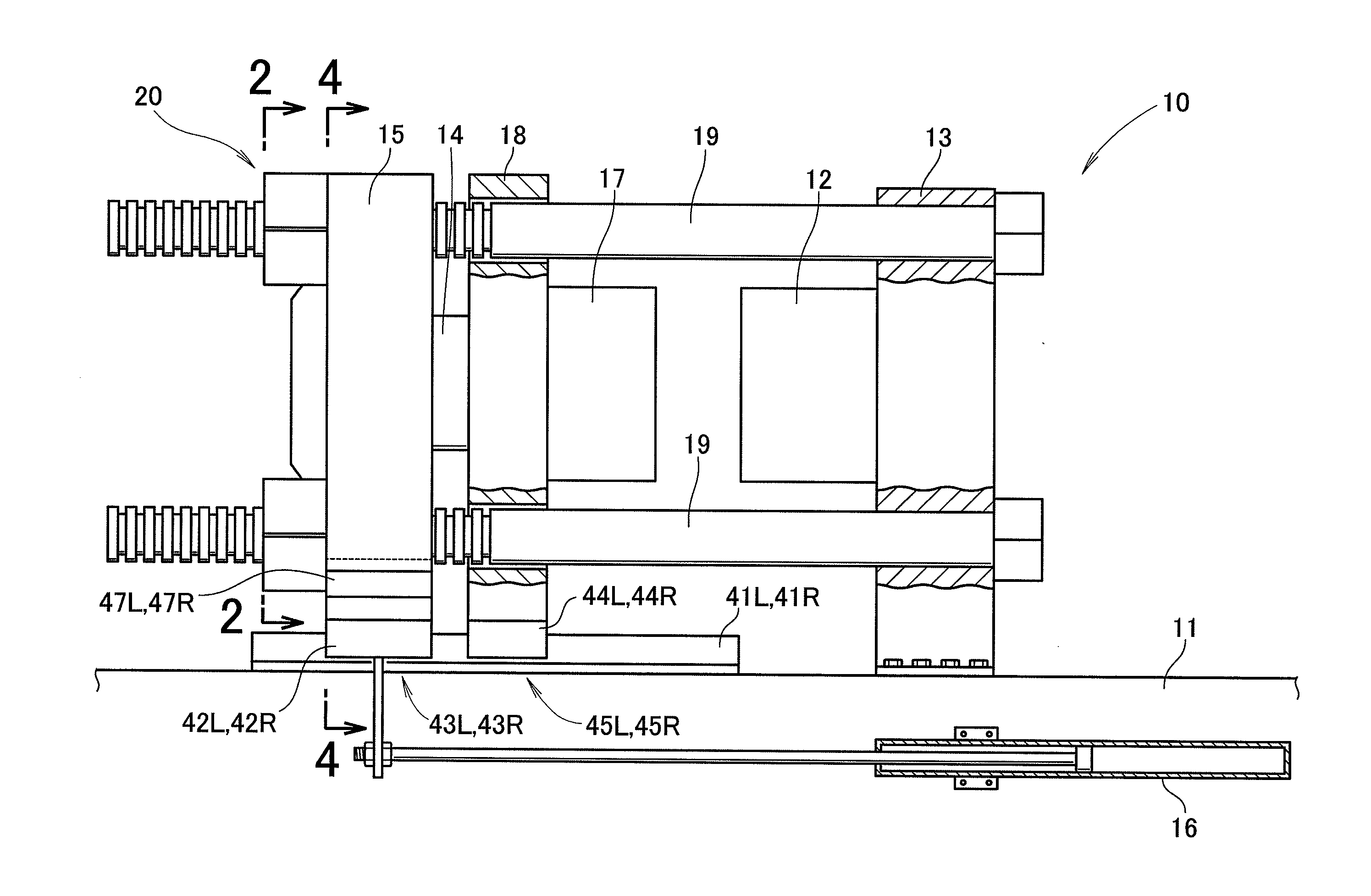
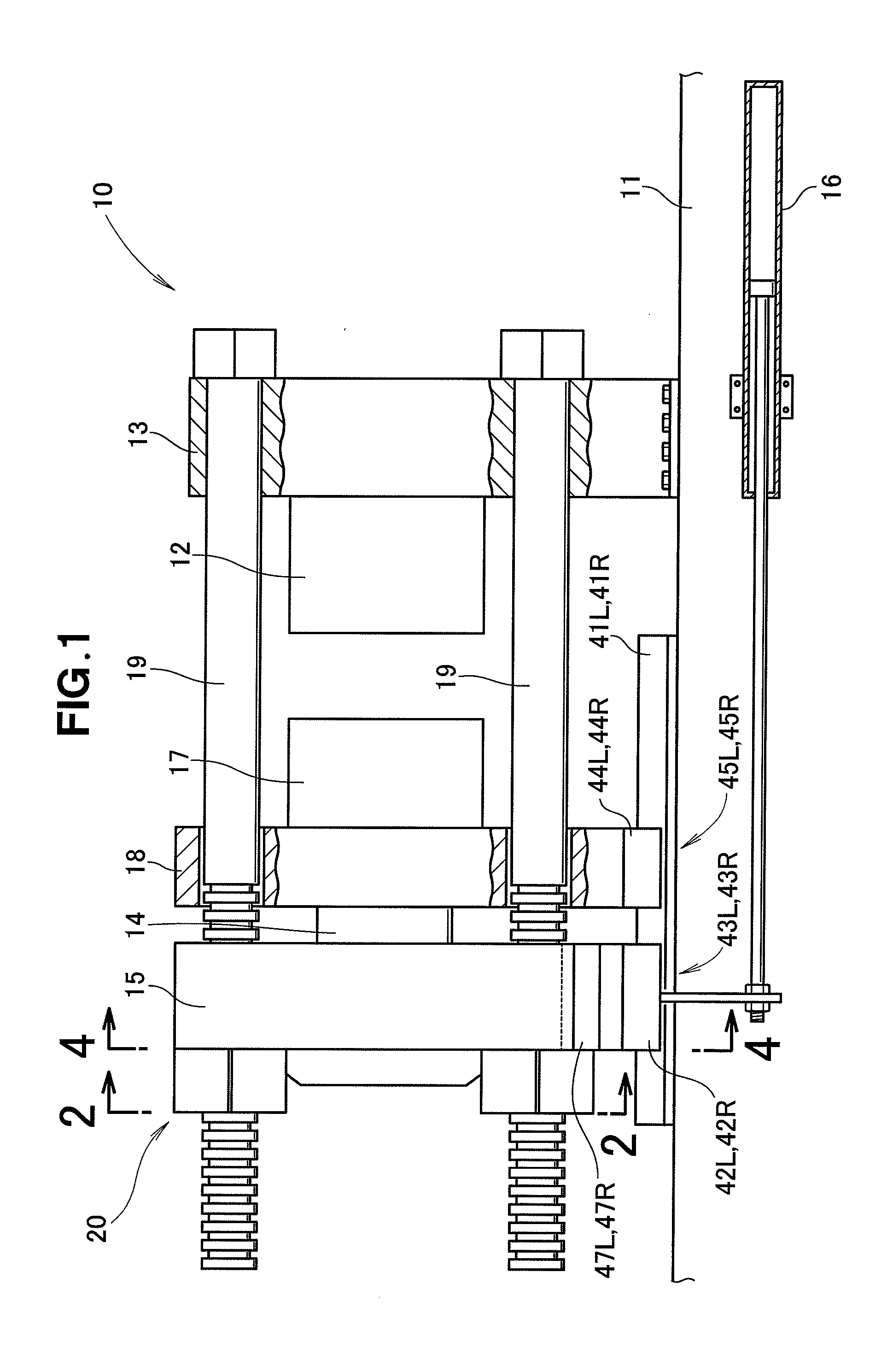
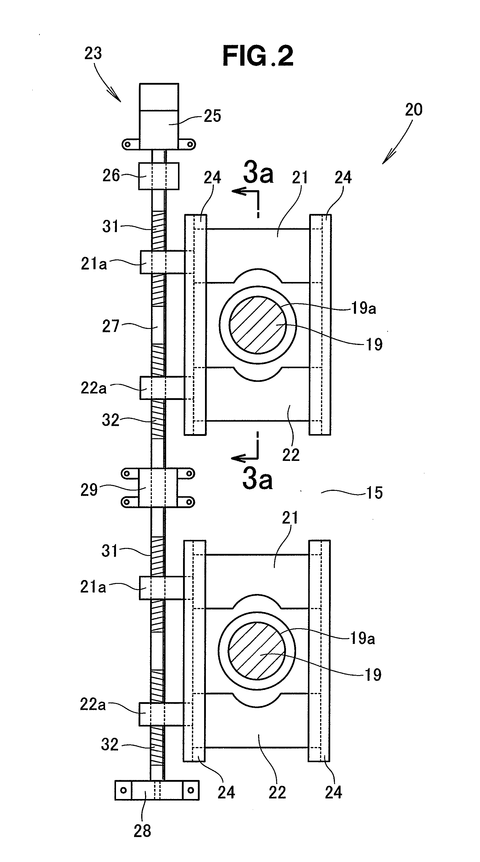
[0024]As shown in FIG. 1, a mold clamping apparatus 10 includes a base 11, a fixed platen 13 fixedly mounted on the base 11 and supporting a fixed mold 12, a mold clamping cylinder 15 disposed parallel to the fixed platen 13 and horizontally movably supported on the base 11, the mold clamping cylinder 15 having a piston rod 14 extending toward the fixed mold 12, a mold opening / closing actuator 16 for moving the mold clamping cylinder 15, a movable platen 18 disposed between the fixed platen 13 and the mold clamping cylinder 15 and connected to the piston rod 14 in such a manner as to be horizontally movably supported on the base 11, the movable platen 18 supporting a movable mold 17, tie bars 19, 19 extending horizontally from the fixed platen 13 and penetrating the movable platen 18 and the mold clamping cylinder 15, and a connecting mechanism 20 arbitrarily connecting the mold clamping cylinder 15 to the tie bars 19, 19.

[0025]Any of a hydraulic cylinder and an electric cylinder ma...


PUM

PropertyMeasurementUnit
Diameteraaaaaaaaaa
Diameteraaaaaaaaaa
Diameteraaaaaaaaaa

Abstract

A mold clamping apparatus includes a fixed platen, a mold clamping cylinder, a movable platen moved by the mold clamping cylinder toward the fixed platen, and a mold opening / closing actuator for moving the movable platen or the mold clamping cylinder. The mold clamping apparatus further includes a mold thickness adjustment cylinder provided between the mold clamping cylinder and the movable platen, the mold thickness adjustment cylinder being configured to generate an axial force larger than an axial force in an expanding direction of the mold opening / closing actuator and smaller than an axial force in a contracting direction of the mold clamping cylinder.

Description

FIELD OF THE INVENTION[0001]The present invention relates to an improvement in a mold clamping apparatus mounted on a horizontal injection molding machine.BACKGROUND OF THE INVENTION[0002]Horizontal injection molding machines mainly comprise a mold clamping apparatus for clamping a mold, and an injecting apparatus for injecting a resin material into the clamped mold. The mold is opened when a molded product is taken out. Generally, mold opening is performed by operating a mold opening / closing actuator which is provided separately from a mold clamping cylinder.[0003]The mold opening / closing actuator has a longer stroke and a smaller cylinder diameter compared to the mold clamping cylinder. When the molded product is large in size, a large mold opening force is required. To increase the mold opening force, it is considered that the cylinder diameter of the mold opening / closing actuator is increased, which, however, makes the mold opening / closing actuator expensive. As one of other mea...

Claims


Application Information

Patent Timeline
IPC IPC(8): B29C45/67B29C45/17
CPCB29C45/67B29C45/1751B29C45/1747B29C45/6728B29C45/6721
Inventor MURATA, ATSUSHITANEMURA, DAIKIYODA, HOZUMITAKAHASHI, NOBUSUKE
Owner NISSEI PLASTIC IND CO LTD
Learn More