Electronic interface control system for a pneumatic vehicle safety lift system

a control system and electronic interface technology, applied in the direction of vehicle maintenance, lifting devices, transportation and packaging, etc., can solve the problem of the crane having a risk of falling, and achieve the effect of improving safety, safe and convenient lifting of the vehicl

Active Publication Date: 2017-03-02
JACKSON SR CLINTON L
View PDF14 Cites 2 Cited by
  • Summary
  • Abstract
  • Description
  • Claims
  • Application Information

AI Technical Summary

Benefits of technology

[0013]Another object is to provide such an electronic control electronic interface control system for a pneumatic vehicle safety lift system that improves safety when a vehicle is lifted by the present invention.
[0014]Another object is to provide such an electronic interface control system for a pneumatic vehicle safety lift system that integrates into a vehicle, such as an automobile, for safe and convenient lifting of the vehicle when aground or stuck, for repairs, for changing a tire, and the like.

Problems solved by technology

As the boom moves and engages its load, the crane has a risk of toppling over.

Method used


Image

  • Electronic interface control system for a pneumatic vehicle safety lift system
  • Electronic interface control system for a pneumatic vehicle safety lift system
  • Electronic interface control system for a pneumatic vehicle safety lift system

Examples


Embodiment Construction

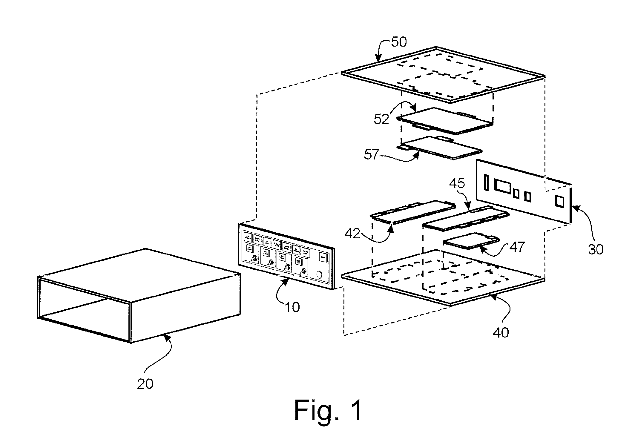
[0041]The present art overcomes the prior art limitations by providing an electronic interface control system for a pneumatic vehicle safety lift system. With reference to the drawings, FIG. 1 shows a detailed exploded view of the invention with an enclosure that houses hardware and other components, as at a housing 20. The enclosure has its construction of metals, polymers, and the like. The housing 20 has a rectangular, hollow, prismatic form. The present invention of the electronic interface control system for a pneumatic vehicle safety lift system provides electronic hardware components as at 42, 45, 47, 52, 57 generally viewed as the computer, or even brain. The components include an input board 42 that collects and reads inputs, and an output board 45 that provides operating outputs based on a program control board 47. The program control board 47 has a sequence of operation of a control for a general purpose of the board 47 of a known type so that the board 47 executes formul...


PUM


Abstract

An electronic interface control system for a pneumatic vehicle safety lift system has a computer that receives sensor inputs, presents outputs, and receives commands from a user. The computer has its power from an automobile and operates an air compressor for air hoses. The computer operates a pneumatic jack upon an automobile. The computer reads sensors related to jack position and triggers indicators to the user so the jack raises the vehicle after a footplate rests below it in a safe manner. The system lifts a vehicle stuck or undergoing repair. The computer checks that a certain number of jacks, preferably one, activate at once. The computer checks by inquiring of the sensors and switches deployed upon a vehicle and within a carrying case. The carrying case has a safety strut for the jack and a torque gun for a user.

Description

CROSS-REFERENCE TO RELATED APPLICATION[0001]This nonprovisional application claims priority to pending non-provisional application Ser. No. 14 / 483143 with a filing date of Sep. 10, 2014 which claims priority to expired provisional application No. 61 / 960104 with a filing date of Sep. 10, 2013 and all are owned by the same inventor.BACKGROUND OF THE INVENTION[0002]The electronic interface control system for a pneumatic vehicle safety lift system generally relates to lifting equipment and more specifically to coordinated jacks mounted upon an automotive vehicle.[0003]For centuries, people walked from place to place usually with shoes. If a shoe had a problem, a person repaired the shoe or bought a new pair of shoes. People then domesticated horses and rode them from place to place. If a horse lost a horseshoe or became lame, people tended to the horse. In the last century, people developed automobiles and light trucks of wide description. People drove them from place to place. Automobi...

Claims


Application Information

Patent Timeline
Patent Type & Authority Applications(United States)
IPC IPC(8): B60S9/10
CPCB60S9/10B60S9/12B66F3/247B66F3/46
Inventor JACKSON, SR., CLINTON L.
Owner JACKSON SR CLINTON L
Why Eureka
Try Eureka