
Vertical Takeoff and Landing Vehicle with Increased Cruise Efficiency

a technology of vertical takeoff and landing vehicle and cruise efficiency, which is applied in the direction of vertical landing/take-off aircraft, efficient propulsion technology, transportation and packaging, etc., can solve the problems of not being able to meet both vtol and cruise efficiency requirements, and achieve the effect of increasing range and enduran

Active Publication Date: 2017-03-02
UNITED STATES OF AMERICA AS REPRESENTED BY THE ADMINISTRATOR NAT AERONAUTICS & SPACE ADMINISTRATION
View PDF0 Cites 17 Cited by
  • Summary
  • Abstract
  • Description
  • Claims
  • Application Information

AI Technical Summary

Benefits of technology

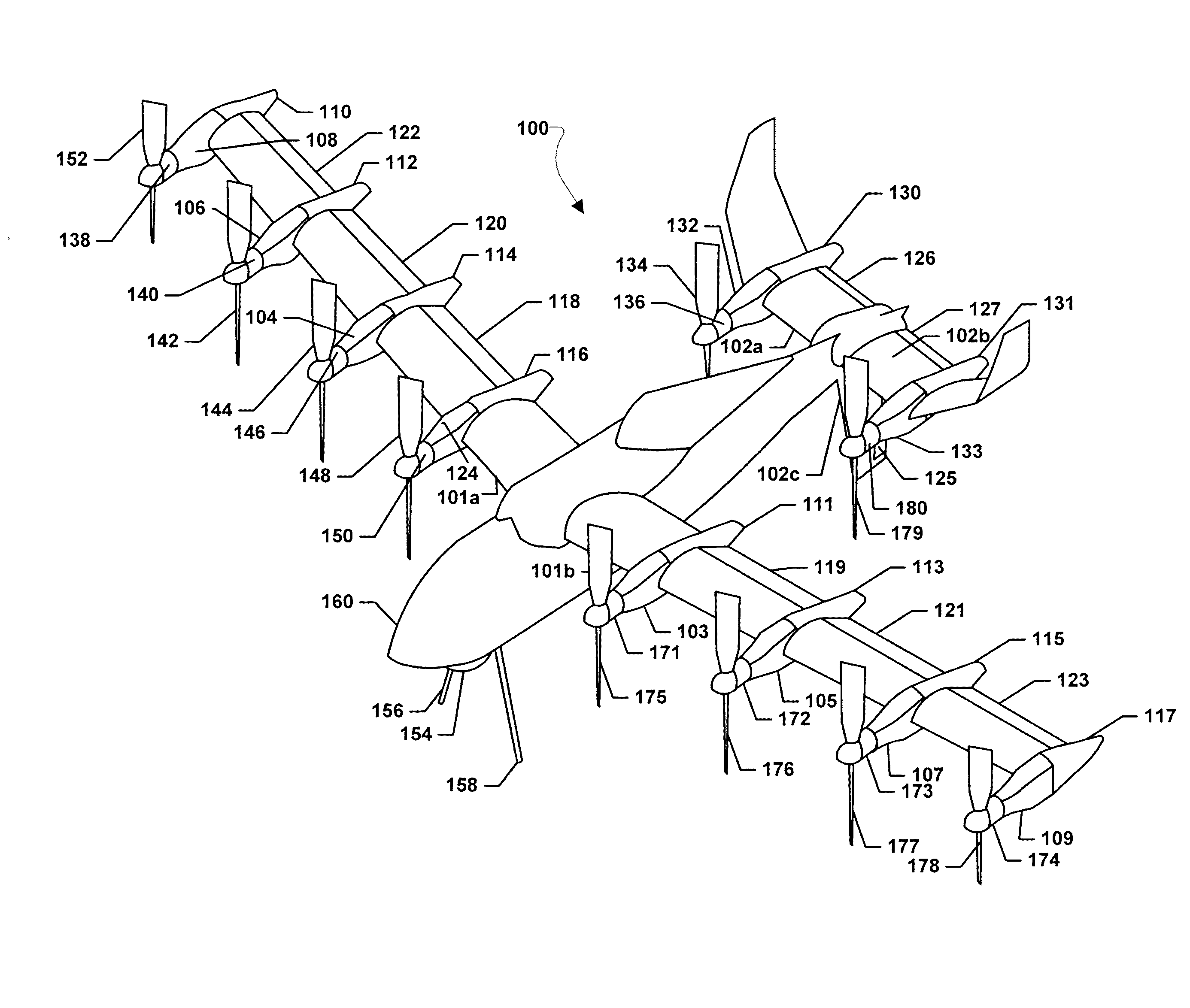
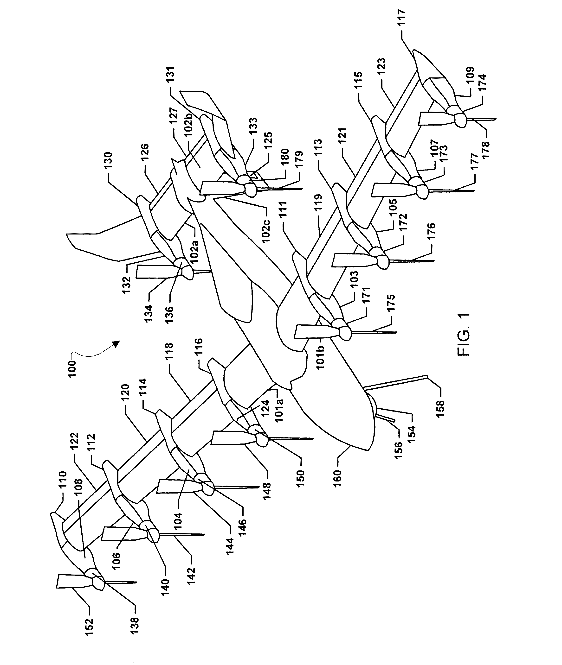
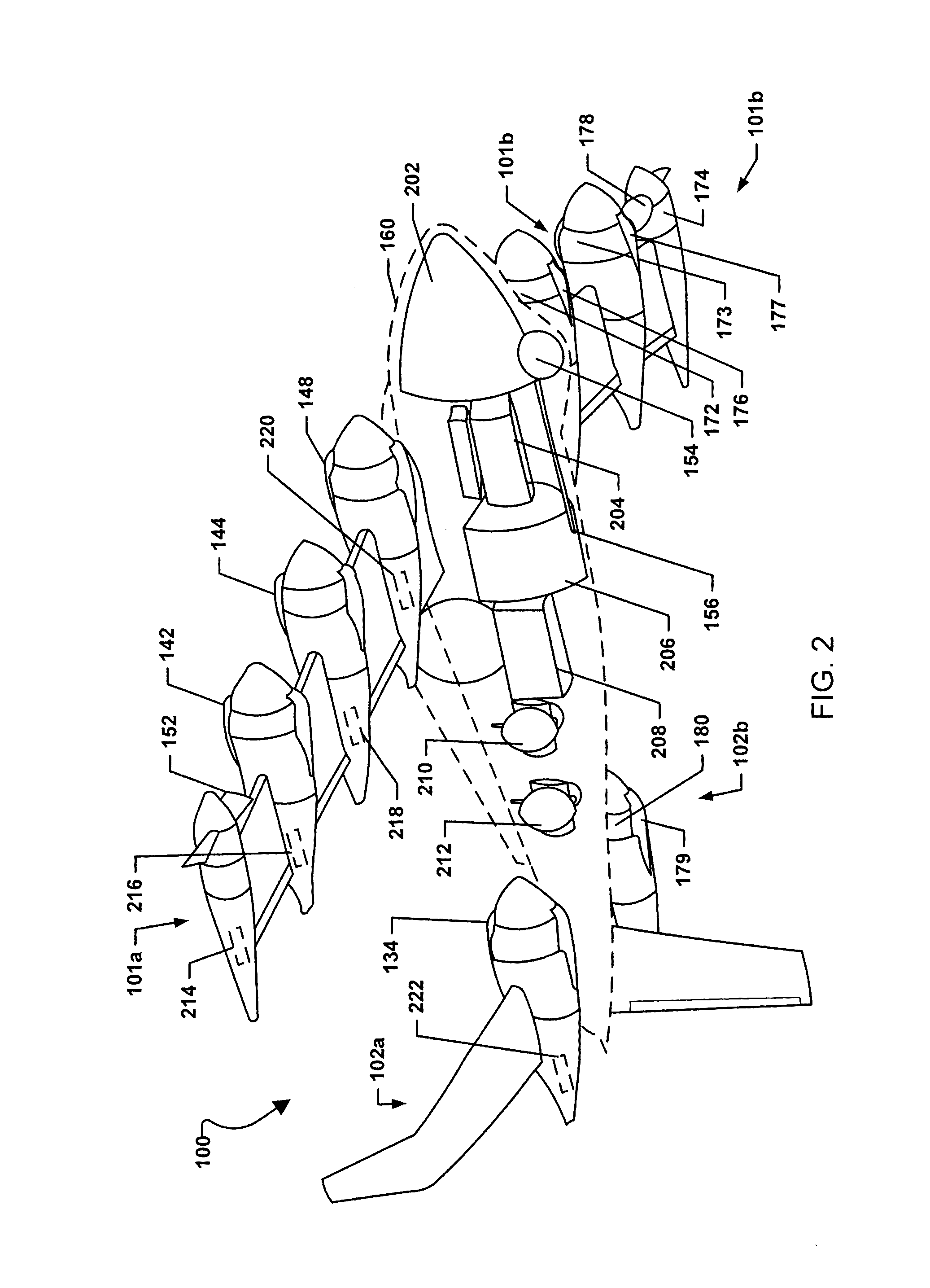
The present invention is a combination of advanced vehicle configuration and electric propulsion that allows for increased range and endurance while maintaining the ability to takeoff and land vertically. The vehicle comprises a tilting wing and tail, and a system of electric motors and propellers to provide efficient VTOL and cruise capabilities without the need for ground infrastructure. The electric system includes one or more batteries and generators powered by internal combustion engines. Overall, the invention provides a vehicle with expanded capabilities and efficiency in both VTOL and cruise flight.

Problems solved by technology

With these current systems it is not possible to meet both VTOL and cruise efficiency requirements without the use of ground infrastructure.

Method used


Image

  • Vertical Takeoff and Landing Vehicle with Increased Cruise Efficiency
  • Vertical Takeoff and Landing Vehicle with Increased Cruise Efficiency
  • Vertical Takeoff and Landing Vehicle with Increased Cruise Efficiency

Examples


Embodiment Construction

[0014]For purposes of description herein, it is to be understood that the specific devices and processes illustrated in the attached drawings, and described in the following specification, are simply exemplary embodiments of the inventive concepts defined in the appended claims. Hence, specific dimensions and other physical characteristics relating to the embodiments disclosed herein are not to be considered as limiting, unless the claims expressly state otherwise.

[0015]The word “exemplary” is used herein to mean “serving as an example, instance, or illustration.” Any implementation described herein as “exemplary” is not necessarily to be construed as preferred or advantageous over other implementations.

[0016]The various embodiments will be described in detail with reference to the accompanying drawings. Wherever possible, the same reference numbers will be used throughout the drawings to refer to the same or like parts. References made to particular examples and implementations are...


PUM


Abstract

Systems, methods, and devices are provided that combine an advance vehicle configuration, such as an advanced aircraft configuration, with the infusion of electric propulsion, thereby enabling a four times increase in range and endurance while maintaining a full vertical takeoff and landing (“VTOL”) and hover capability for the vehicle. Embodiments may provide vehicles with both VTOL and cruise efficient capabilities without the use of ground infrastructure. An embodiment vehicle may comprise a wing configured to tilt through a range of motion, a first series of electric motors coupled to the wing and each configured to drive an associated wing propeller, a tail configured to tilt through the range of motion, a second series of electric motors coupled to the tail and each configured to drive an associated tail propeller, and an electric propulsion system connected to the first series of electric motors and the second series of electric motors.

Description

CROSS-REFERENCE TO RELATED PATENT APPLICATIONS[0001]This patent application is a continuation of U.S. patent application Ser. No. 14 / 121,001, filed Aug. 13, 2014, which claims the benefit of and priority to U.S. Provisional Patent Application No. 61 / 865,347, filed on Aug. 13, 2013. The contents of each of the foregoing applications are hereby incorporated by reference in their entireties.STATEMENT REGARDING FEDERALLY SPONSORED RESEARCH OR DEVELOPMENT[0002]The invention described herein was made in part by employees of the United States Government and may be manufactured and used by or for the Government of the United States of America for governmental purposes without the payment of any royalties thereon or therefore.BACKGROUND OF THE INVENTION[0003]Vertical takeoff and landing (“VTOL”) and cruise efficiency are diametrically opposed requirements for aircraft. There are system solutions today that require ground infrastructure, namely catapults and arresting equipment, to launch and...

Claims


Application Information

Patent Timeline
Patent Type & Authority Applications(United States)
IPC IPC(8): B64C29/00B64D27/24B64D27/26B64C5/02B64C11/28B64C25/52B64C39/02B64C3/38B64C11/50B64C9/14
CPCB64C29/0033B64C2201/165B64D27/24B64D27/26B64C9/14B64C11/28B64C25/52B64C39/024B64C3/385B64C5/02B64C2201/021B64C2201/042B64C2201/088B64C2201/108B64C11/50B64C25/32Y10S903/903Y02T50/60Y02T50/40B64U70/80B64U30/10B64U50/19B64U50/13B64D27/026B64C3/40B64U10/25B64U30/20B64U50/11B64D27/40
Inventor FREDERICKS, WILLIAM J.MOORE, MARK D.BUSAN, RONALD C.ROTHHAAR, PAUL M.NORTH, DAVID D.LANGFORD, WILLIAM M.LAWS, CHRISTOPHER T.HODGES, WILLIAM TJOHNS, ZACHARY R.WEBB, SANDY R.
Owner UNITED STATES OF AMERICA AS REPRESENTED BY THE ADMINISTRATOR NAT AERONAUTICS & SPACE ADMINISTRATION
Learn More