Low Profile Lighting Fixture With Movable Heat Sink And Lighting Element Assembly

a technology of low-profile lighting fixtures and heat sinks, which is applied in the direction of fixed installation, lighting and heating equipment, lighting support devices, etc., can solve the problem of difficult service of these components

Active Publication Date: 2017-03-02
USAI LLC
View PDF5 Cites 63 Cited by
  • Summary
  • Abstract
  • Description
  • Claims
  • Application Information

AI Technical Summary

Benefits of technology

[0005]It is therefore an object of the present technology to provide a recessed light fixture with a low profile that will allow a user to access the electrical components, including the lighting driver, for maintenance through the illumination aperture. Effectively, maintenance of the lighting driver and other electrical wires and components can be accomplished using a similar process as is commonly used to change a burned out bulb.
[0006]To accomplish its objectives, the present technology provides a low-profile light fixture with a housing, a lighting element enclosure, and a junction box. A base of the housing has an illumination aperture through which maintenance can be performed. The lighting element enclosure is preferably a substantially rectangular or square shaped box with no bottom. The top of the lighting element enclosure is preferably formed by the base of a heat sink, the base of the heat sink having a plurality of fins extending upwardly therefrom. A lighting element is disposed within the lighting element enclosure and is preferably mounted to the base of the heat sink, forming an assembly of the heat sink and the lighting element. Mounting the lighting element to the heat sink directly maximizes the effectiveness of the heat dissipation function of the heat sink.
[0012]It is preferable to have the telescoping portion abut the top of the junction box both because it more effectively encloses the internal components of the light fixture and because it maximizes the height between the horizontal top wall of the telescoping portion and the base of the housing, allowing the lighting driver and other electrical components to be removed from the junction box through the illumination aperture. More specifically, when the heat sink is in the service position, the telescoping portion will be vertically aligned with the illumination aperture, at least in part. Thus it is important to accomplish the objectives of the present technology that the distance between the horizontal top wall of the telescoping portion and the base of the housing is sufficiently great to permit access to and removal of the lighting driver.
[0015]In some embodiments, the junction box may employ a mount for the lighting driver using opposing rails to suspend the lighting driver within the junction box. In such embodiments, the mount is preferably affixed to the heat sink such that it shifts with the heat sink between the operation and service positions. Such embodiments further preferably employ a lighting driver bracket with projections to engage the opposing rails, with the lighting driver attached thereto. Thus, in such preferable embodiments, the lighting driver actually shifts along with the heat sink, bringing it closer to the illumination aperture when the heat sink is in the service position and facilitating its removal through the illumination aperture.
[0021]To maximize the heat sink's effectiveness, preferable embodiments employ an assembly whereby the lighting element is attached directly to the base of the heat sink. In such embodiments, the heat sink, lighting element, and lighting element enclosure all operate as a single, movable unit within the housing. This assembly can be shifted between an operation position, an intermediate position, and a service position. The guide rails of the housing directs the assembly between the three positions, ensuring continued operability of the light fixture after maintenance.
[0027]With the junction box vertically aligned with the illumination aperture, the user has access to the bottom of the junction box. In preferable embodiments, the bottom of the junction box has a removable plate behind which is a hole to access the inside of the junction box, which contains the lighting driver and other electrical components. The user can remove the cover plate and remove the lighting driver for service through the illumination aperture without removing the light fixture from behind the wall or ceiling, thereby accomplishing the objectives of the technology.

Problems solved by technology

Recessed lighting is very popular in residential and commercial buildings given its unobtrusive and aesthetically pleasing appearance.
Servicing these components can be problematic when the components are all disposed out of sight and reach.

Method used


Image

  • Low Profile Lighting Fixture With Movable Heat Sink And Lighting Element Assembly
  • Low Profile Lighting Fixture With Movable Heat Sink And Lighting Element Assembly
  • Low Profile Lighting Fixture With Movable Heat Sink And Lighting Element Assembly

Examples


Embodiment Construction

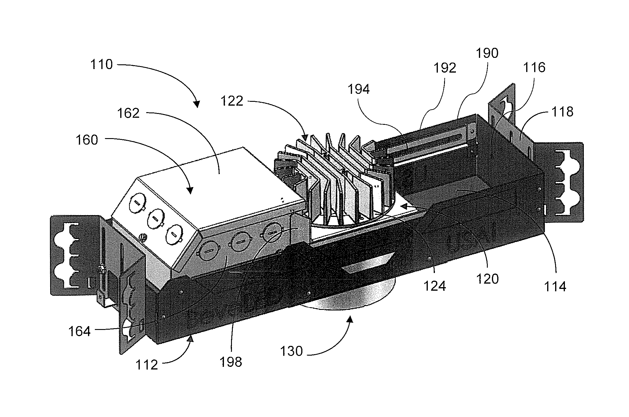
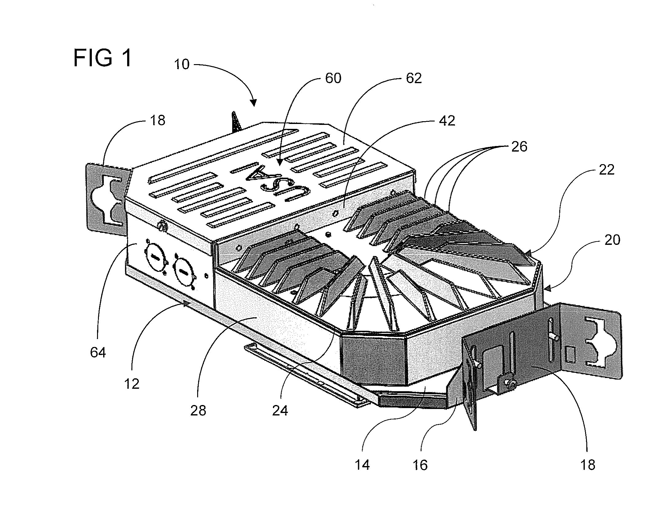
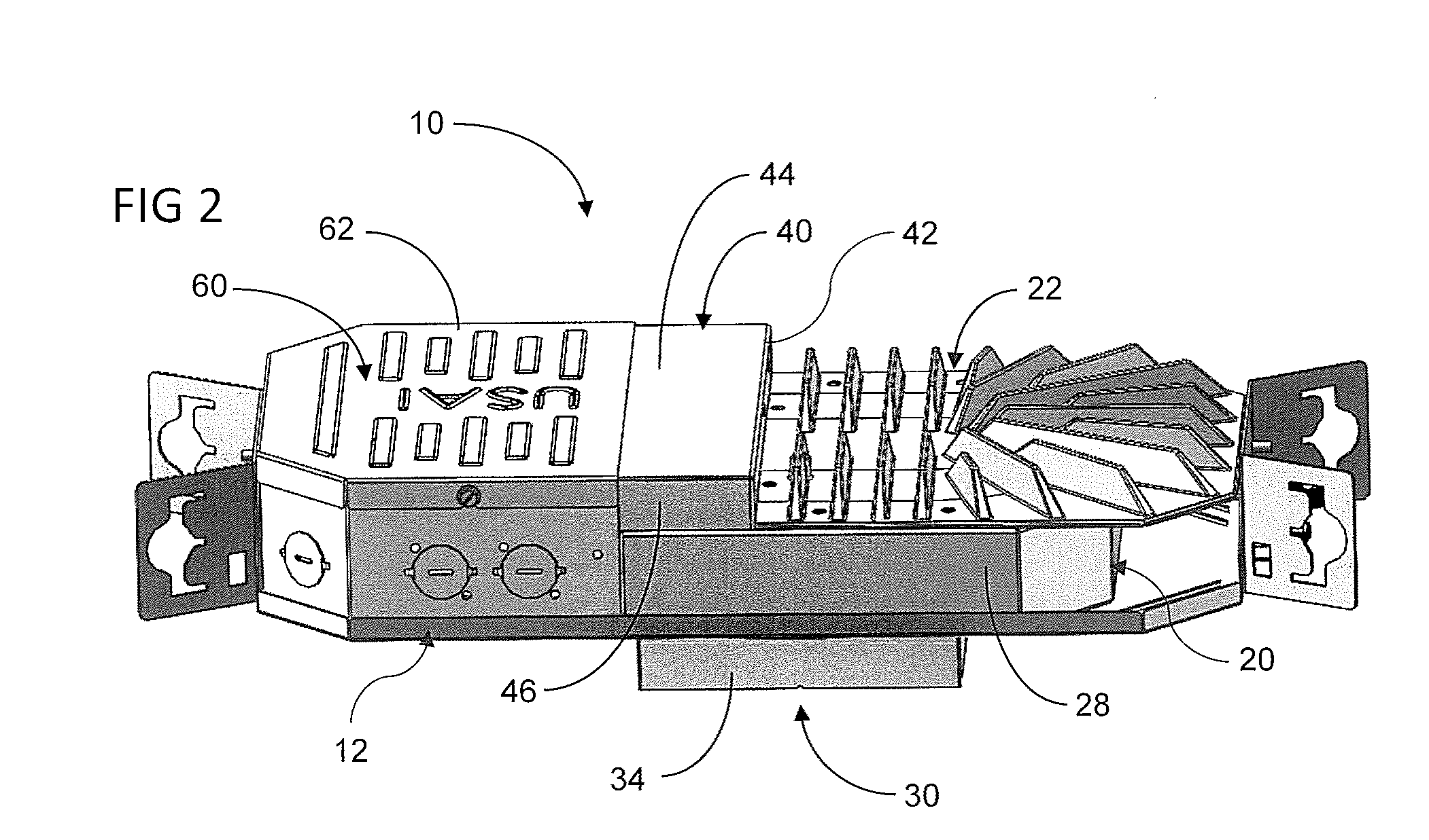
[0060]The following detailed description illustrates the technology by way of example, not by way of limitation of the principles of the invention. This description will enable one skilled in the art to make and use the technology, and describes several embodiments, adaptations, variations, alternatives, and uses of the invention, including what is presently believed to be the best mode of carrying out the invention. One skilled in the art will recognize alternative variations and arrangements, and the present technology is not limited to those embodiments described hereafter. The low profile light fixture disclosed herein is described as if oriented in a manner to be installed in a horizontal ceiling, using terms such as vertical, horizontal, upper, lower, etc. However, it is to be understood that the light fixture can be placed and used in other orientations, such as vertical walls or other non-horizontal surfaces.

[0061]The low profile lighting fixture disclosed herein is particul...


PUM


Abstract

A low-profile, recessed light fixture with a housing, a lighting element enclosure with a heat sink, and a junction box containing a lighting driver. The base of the housing has an illumination aperture disposed therein. The heat sink acts as the top of the lighting element enclosure and is movable between an operation position and a service position. In the operation position, the heat sink is vertically aligned with the illumination aperture. In the service position, the heat sink is horizontally displaced from vertical alignment with the illumination aperture. When the heat sink is in the service position, the interior of the junction box is accessible through the illumination aperture, allowing the user to remove the lighting driver and other electrical components from the junction box for maintenance.

Description

FIELD OF THE INVENTION[0001]The present technology relates to the field of recessed lighting fixtures. More specifically, the present technology discloses a low-profile recessed lighting fixture with convenient maintenance accessibility without detaching the fixture from the building's structure.BACKGROUND OF THE INVENTION[0002]Recessed lighting is very popular in residential and commercial buildings given its unobtrusive and aesthetically pleasing appearance. Recessed lighting removes from view all electric hardware and wiring, placing everything behind a wall or ceiling. However, the electrical components that power the light fixtures must be serviced from time-to-time, particularly the lighting driver that controls and powers the light source. Servicing these components can be problematic when the components are all disposed out of sight and reach.[0003]Accordingly, there is a need in the art for a recessed light fixture that permits the user access to the electrical components, ...

Claims


Application Information

Patent Timeline
Patent Type & Authority Applications(United States)
IPC IPC(8): F21V17/02F21V23/00F21S8/02F21V23/06F21V17/18F21V7/00F21V29/74F21V17/12
CPCF21V17/02F21V29/74F21V23/003F21V17/12F21Y2115/10F21V17/18F21V7/00F21S8/02F21V23/06F21V17/002F21V21/34F21V23/007F21V29/763
Inventor JONES, JONATHAN I.
Owner USAI LLC
Why Eureka
Try Eureka