
Vehicle display device

a technology for display devices and vehicles, applied in control devices, vehicle components, instruments, etc., can solve the problems of decreased workability in attachments and increased parts, and achieve the effect of reducing the parallax caused by the dark reflected image and improving the visibility of the reflected image (virtual image) of the display imag

Active Publication Date: 2017-03-02
YAZAKI CORP
View PDF5 Cites 22 Cited by
  • Summary
  • Abstract
  • Description
  • Claims
  • Application Information

AI Technical Summary

Benefits of technology

The vehicle display device described in this patent helps to prevent dark visual recognition of reflected images, such as from the instrument panel, transmission unit, and frame unit. This reduces the feeling of strangeness for passengers and improves the visibility of the reflected image. The invention includes various methods for reducing parallax and improving the display image.

Problems solved by technology

However, because the vehicle display device 5800 includes the light guide member 5803 and parts for supporting the light guide member 5803, the number of parts is increased, and thus there is a problem of a decrease in workability in attachment.

Method used


Image

  • Vehicle display device
  • Vehicle display device
  • Vehicle display device

Examples


first embodiment

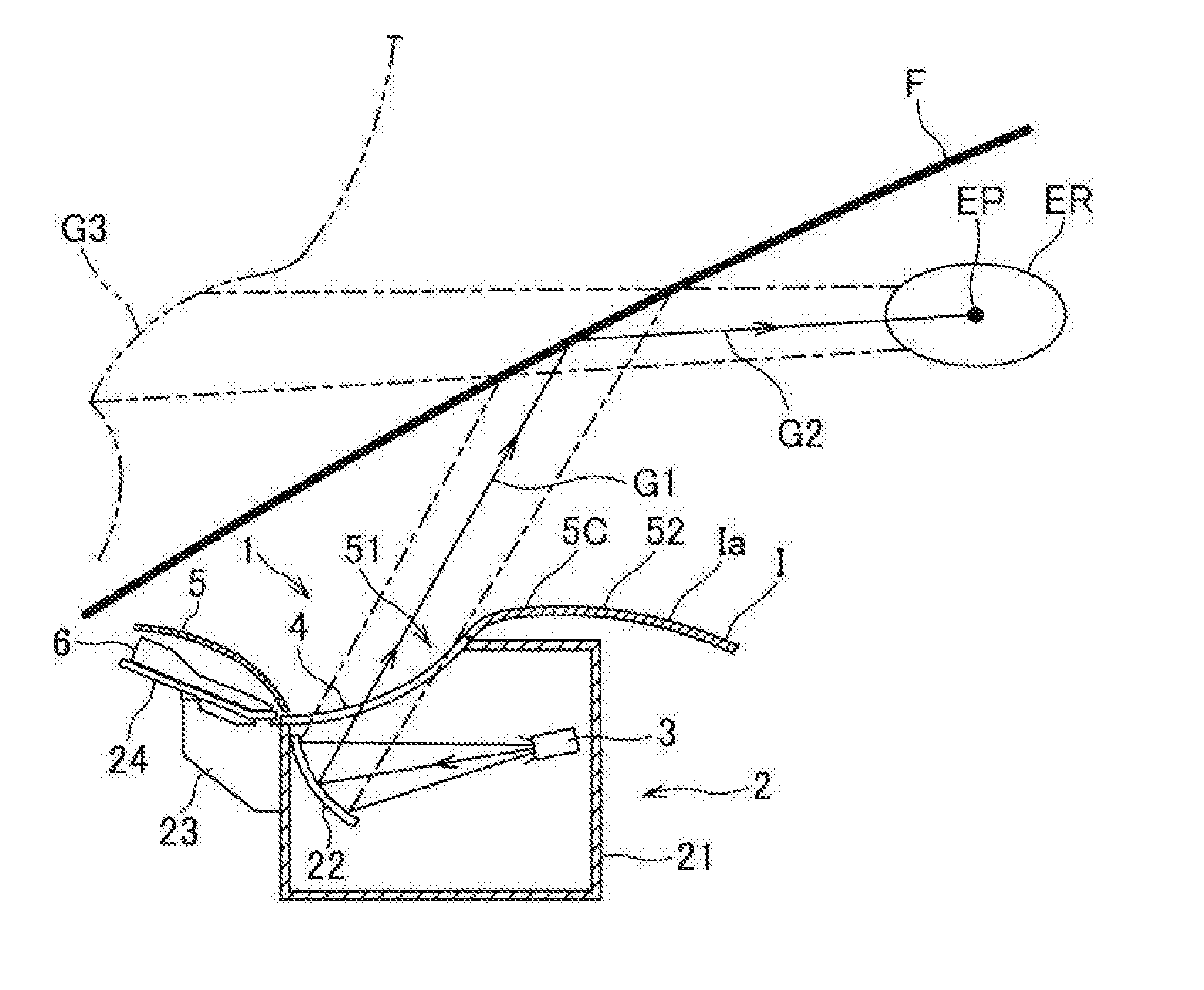
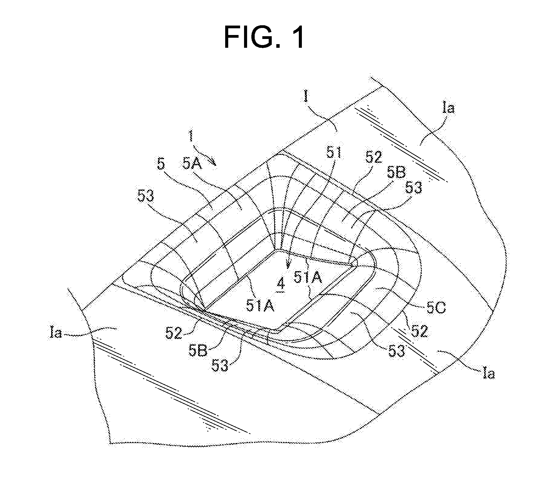
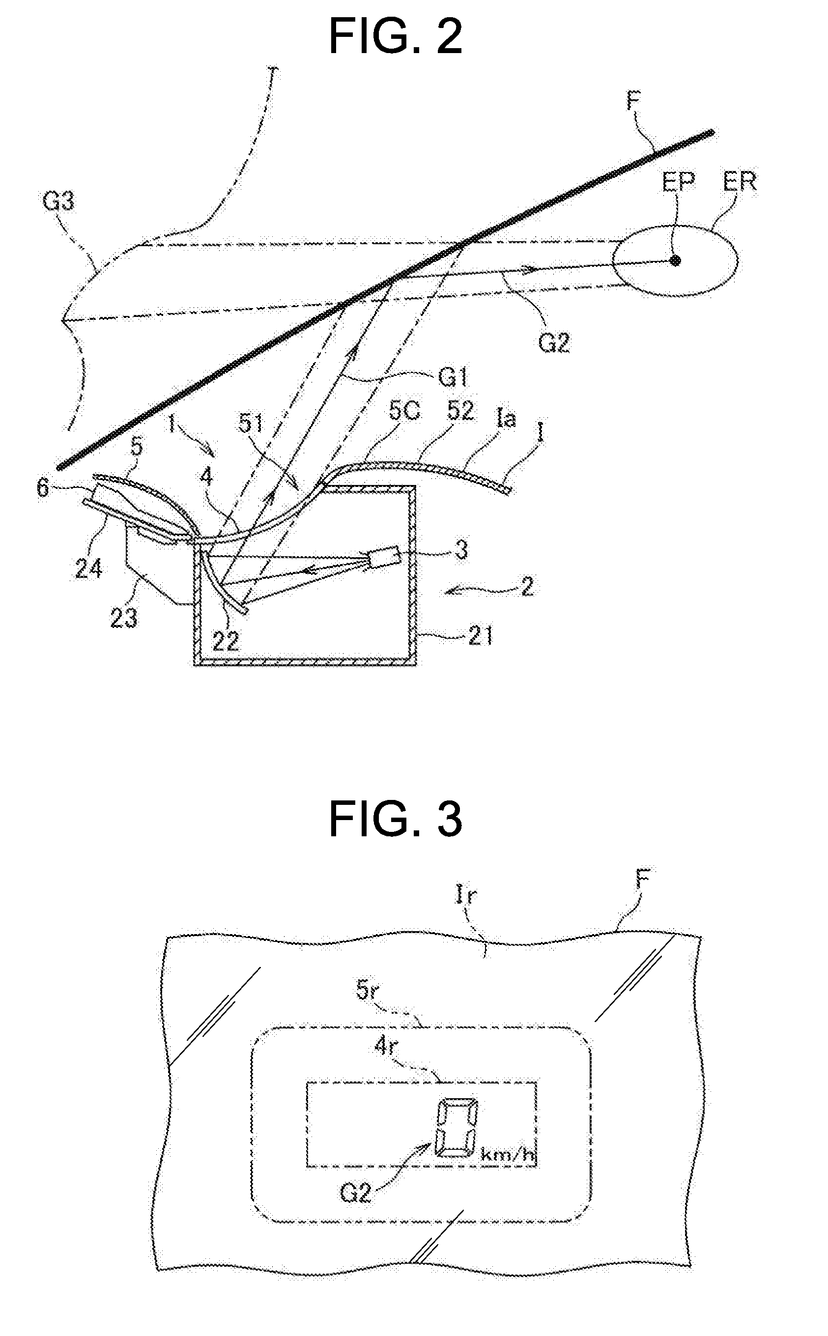
[0163]A vehicle display device and a bezel body according to a first embodiment of the present invention will be described with reference to FIGS. 7 to 10.

[0164]A vehicle display device 2001 of the present embodiment is used as a head-up display device attached to an instrument panel I2000 of a vehicle V2000 and which performs projection on a windshield F2000, and includes an image projector 2010 and a bezel body 2020. Note that, in the present embodiment, an up and down direction, a front and rear direction, and a right and left direction correspond to an up and down direction, a front and rear direction, and a right and left direction of the vehicle V2000.

[0165]As illustrated in FIGS. 7 and 8, the image projector 2010 is provided with a display source 2011, a reflection portion 2012 that reflects an image from the display source 2011, and a housing 2013 in which the display source 2011 and the reflection portion 2012 are accommodated. The housing 2013 is formed in a box shape, usi...

second embodiment

[0176]A vehicle display device according to a second embodiment of the present invention will be described with reference to FIGS. 10 to 17. Note that, in the present embodiment, the same configuration portions as those in the first embodiment are denoted with the same reference signs and description is omitted.

[0177]A vehicle display device of the present embodiment is used as a head-up display device attached to an instrument panel I2000 of a vehicle V2000, and which performs projection on a windshield F2000. The vehicle display device includes an image projector 2010 (see FIGS. 7 and 8) and a bezel body 2030.

[0178]As illustrated in FIG. 12, the bezel body 2030 includes a bezel member 2031 fit in a hole K2000 provided in a facing wall A2000 of the instrument panel I2000, the facing wall A2000 facing the windshield F2000, alight source unit 2022 that emits light toward the bezel member 2031, and a cover 2023 attached to an opening 2313 provided in the bezel member 2031 and describe...

third embodiment

[0188]A vehicle display device 3 according to a third embodiment of the present invention will be described with reference to FIGS. 18 to 21. Note that, in the present embodiment, the same configuration portions as those in the first embodiment are denoted with the same reference signs and description is omitted.

[0189]The vehicle display device 3 of the present embodiment is used as a head-up display device attached to an instrument panel I2000 of a vehicle V2000, and which performs projection on a windshield F2000. The vehicle display device 3 includes an image projector 2010 (see FIGS. 7 and 8) and a bezel body 2040.

[0190]The bezel body 2040 includes a bezel member 2041 fit in a hole K2000 provided in a facing wall A2000 of the instrument panel I2000, the facing wall A2000 facing the windshield F2000, alight source unit 2022 that emits light toward the bezel member 2041, and a cover 2023 attached to an opening 2413 provided in the bezel member 2041 and described below (see FIGS. 7...


PUM


Abstract

Provided is a vehicle display device that can improve visibility without providing a feeling of strangeness to a passenger. A vehicle display device includes a display unit provided in an inner side of an instrument panel and which projects a display image, a transparent cover that transmits the display image projected from the display unit toward a windshield, and a bezel body including an opening portion that allows the display image transmitted through the transparent cover to pass through and having an outer edge portion continuing into the windshield, and the degrees of brightness of respective reflected images of the instrument panel, the transparent cover, and the bezel body, the respective reflected images being reflected in the windshield, are made uniform, and therefore dark visual recognition of any of the reflected images is suppressed, and the feeling of strangeness provided to the passenger is relieved.

Description

TECHNICAL FIELD[0001]The present invention relates to a vehicle display device provided in an instrument panel, projects a display image on a windshield, and causes a passenger to visually recognize a virtual image of the display image reflected on the windshield.BACKGROUND ART[0002]Conventionally, as a vehicle display device, a head-up display (HUD) device has been proposed, which projects a display image from a projector provided inside an instrument panel, on a windshield, reflects the projected display image on the windshield, and causes a passenger to visually recognize a reflected image thereof as a virtual image (for example, see Patent Literature 1). In the vehicle display device described in Patent Literature 1, a transparent cover that transmits the display image is provided on an opening portion of the instrument panel, and dust and the like do not enter inside the device with the transparent cover.CITATION LITPatent Literature[0003]Patent Literature 1: JP 2007-148092 ASU...

Claims


Application Information

Patent Timeline
Patent Type & Authority Applications(United States)
IPC IPC(8): G02B27/01B60K35/00
CPCG02B27/0101B60K35/00B60K2350/92B60K2350/2052G02B2027/0118B60K2350/2069B60K2350/1068B60K2350/2095B60K2350/1072B60K37/00B60K35/213B60K35/23B60K2360/349B60K2360/334B60K35/29B60K2360/27B60K2360/184
Inventor TAKAHASHI, NOBUYUKI
Owner YAZAKI CORP
Learn More