Hub for a wind turbine and a method for fabricating the hub
a technology for wind turbines and hubs, which is applied in the direction of motors, wind energy generation, climate sustainability, etc., can solve the problems of large parts that are difficult to handle during manufacture, cranes which are normally used for this purpose will not be able to lift a casing including sand and casted parts, and forces to act on the casted parts, etc., to achieve the effect of convenient arrangemen
Inactive Publication Date: 2017-03-09
VESTAS WIND SYST AS
View PDF1 Cites 1 Cited by
- Summary
- Abstract
- Description
- Claims
- Application Information
AI Technical Summary
Benefits of technology
The solution enables efficient manufacturing and transportation of large hubs with reduced manual labor, improved weight distribution, and enhanced strength and stiffness, addressing the challenges of handling and transporting large wind turbine components.
Problems solved by technology
The large parts are difficult to handle during manufacture as well as during transport from the manufacturing facility to the operating site of the wind turbine.
In the case that the part being casted is relatively large and heavy, the cranes which are normally used for this purpose will not be able to lift a casing including sand and casted part.
Furthermore, the buoyancy of the sand causes forces to act on the casted part.
If very large parts are casted, the amount of sand is also very large, and the forces acting on the casted part may thereby become excessive.
Furthermore, moving large wind turbine parts, such as hubs, is very difficult.
The vehicles used for moving the parts must be very large, and it may be difficult to maneuver such vehicles on normal roads, and it may disturb the normal traffic.
The vehicles must also be able to carry the weight of the parts, and the weight distribution along the vehicle may be uneven, thereby posing further demands to the vehicle.
Finally, handling of large wind turbine parts at the manufacturing site and on the operating site of the wind turbine is difficult, simply due to the large size and high weight of the parts.
The hub core is a relatively large part, and the disadvantages regarding handling and manufacture of large parts are therefore not fully avoided by this hub.
Method used
View moreImage
Smart ImageViewing Examples

Examples
first embodiment
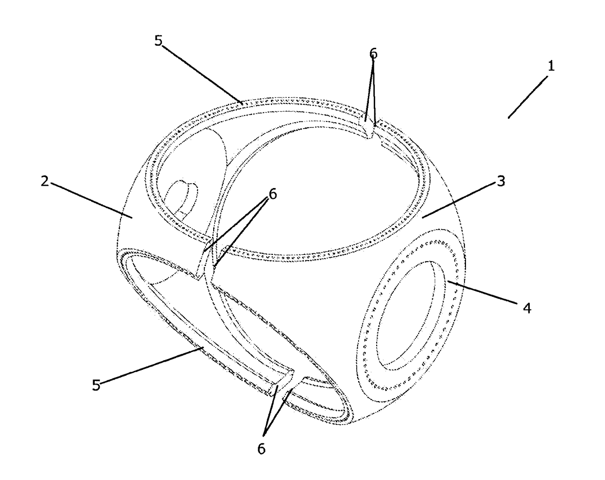
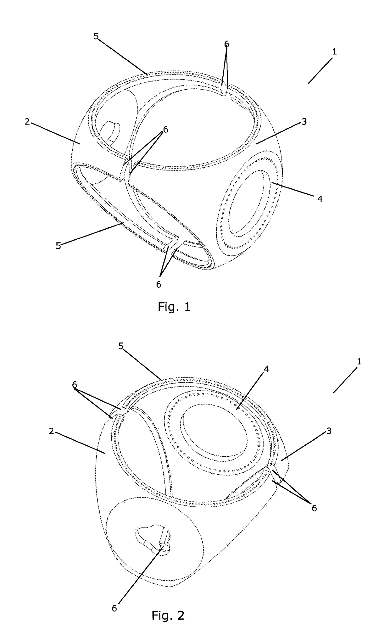
[0059]FIGS. 1 and 2 are exploded views of a hub according to the invention,
second embodiment
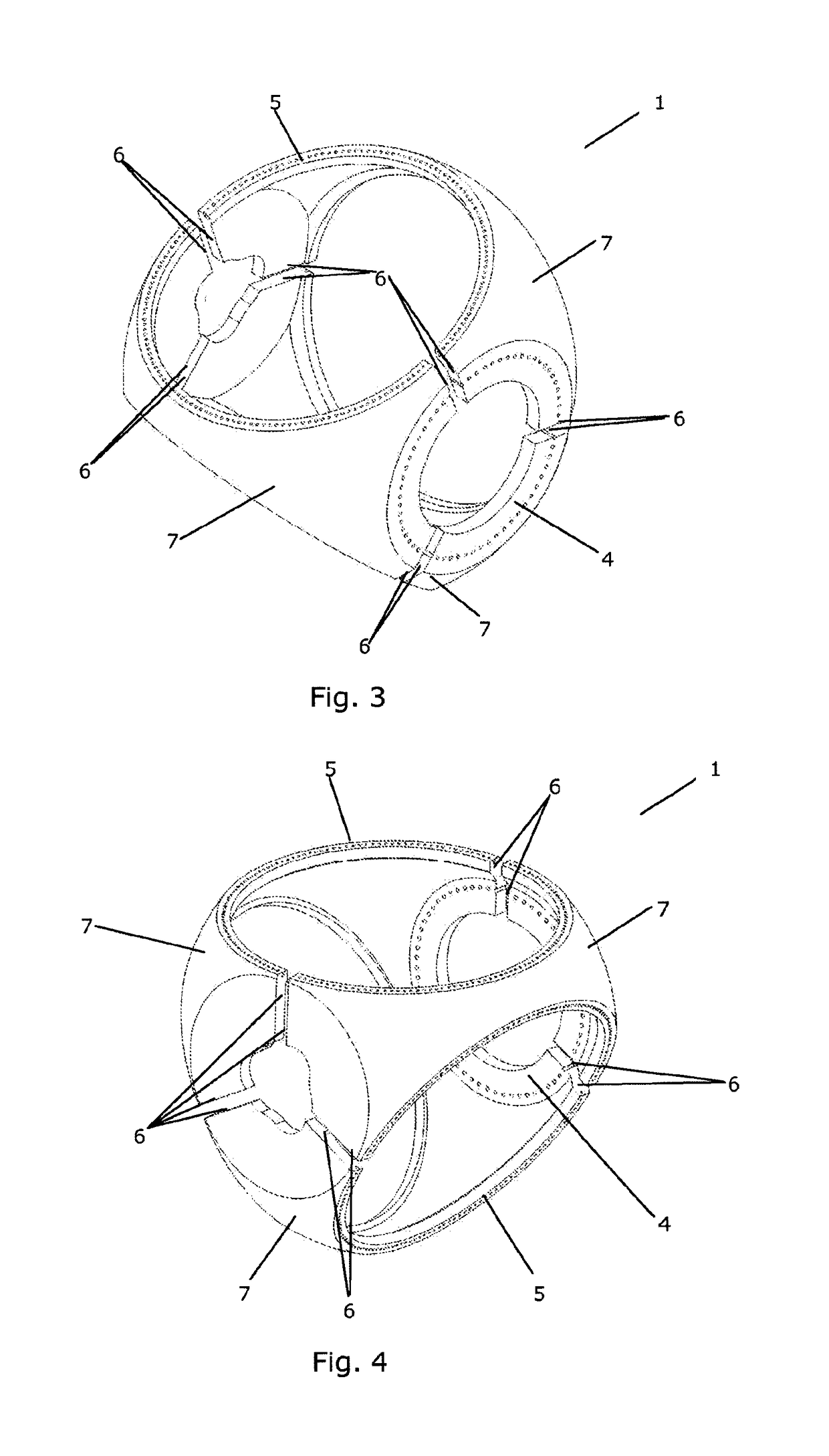
[0060]FIGS. 3 and 4 are exploded views of a hub according to the invention,
third embodiment
[0061]FIGS. 5 and 6 are exploded views of a hub according to the invention,
Login to View More PUM
| Property | Measurement | Unit |
|---|---|---|
| size | aaaaa | aaaaa |
| buoyancy | aaaaa | aaaaa |
| forces | aaaaa | aaaaa |
Abstract
A hub for a wind turbine and a method for fabricating the hub are disclosed. The hub comprises a continuous shell forming a hollow body with a main shaft flange adapted to connect the hub to a main shaft, and one or more blade flanges, each blade flange being adapted to connect the hub to a wind turbine blade. The hub further comprises at least two hub parts, each hub part being casted separately from a castable material, and each hub part being subsequently connected to at least one other hub part via one or more connecting portions, so that at least one blade flange and / or the main shaft flange comprises a section forming part of or being attached to one of the hub parts and a section forming part of or being attached to another hub part, thereby ensuring that the casted parts have a size and a weight which are manageable during the manufacture, in particular during the casting. The hub may comprise one or more reinforcement elements arranged at or near the blade flange(s), e.g., comprising an inner wall arranged at a distance to the continuous shell, thereby forming a cavity between the inner wall and the continuous shell. This allows the regions between the blade flanges to be small or narrow, thereby reducing the size and weight of the hub, while maintaining a sufficient strength and stiffness of these regions.
Description
CROSS REFERENCE TO RELATED APPLICATIONS[0001]This application is a continuation of U.S. patent application Ser. No. 13 / 517,191, filed Mar. 29, 2013 (pending), which is a U.S. National Phase Application of International Application No. PCT / EP2010 / 070387, filed Dec. 21, 2010 (expired), which designates the United States and claims priority to Danish Patent Application No. PA 2009 70287 filed Dec. 21, 2009. PCT / EP2010 / 070387 also claims priority from U.S. Provisional Application No. 61 / 288,617, filed Dec. 21, 2009 (expired). Each of these applications is incorporated by reference herein in their entirety.FIELD OF THE INVENTION[0002]The present invention relates to a hub for a wind turbine. The hub of the invention is easy to handle during fabrication and transport, even if the size of the hub is very large. The invention further relates to a method for fabricating such a hub.BACKGROUND OF THE INVENTION[0003]In the wind power industry there is a tendency to produce wind turbines of incr...
Claims
Login to View More Application Information
Patent Timeline
 Patent Type & Authority Applications(United States)
IPC IPC(8): F03D1/06B23P15/04
CPCF03D1/0691F05B2230/21B23P15/04Y10T29/49826Y02E10/72Y02P70/50B23P15/00
Inventor BECH, ANTONBITSCH, MICHAEL LUNDGAARD
Owner VESTAS WIND SYST AS
Features
- R&D
- Intellectual Property
- Life Sciences
- Materials
- Tech Scout
- Unparalleled Data Quality
- Higher Quality Content
- 60% Fewer Hallucinations
Learn More Browse by: Latest US Patents, China's latest patents, Technical Efficacy Thesaurus, Application Domain, Technology Topic, Popular Technical Reports.
© 2025 PatSnap. All rights reserved.Legal|Privacy policy|Modern Slavery Act Transparency Statement|Sitemap|About US| Contact US: help@patsnap.com