Surgical control device, control method, and imaging control system

a control device and control method technology, applied in the direction of surgical microscopes, instruments, surgical instrument support, etc., can solve the problems of difficult to obtain a focused image of the observation target intended by the surgeon, and the surgical operation efficiency deteriorates

Active Publication Date: 2017-03-09
SONY CORP
View PDF11 Cites 18 Cited by
  • Summary
  • Abstract
  • Description
  • Claims
  • Application Information

AI Technical Summary

Benefits of technology

[0013]According to the first and second embodiments of the present disclosure, it is possible to control the imaging. In addition, according to the first and second embodiments of the present disclosure, it is possible to obtain a focused image with an imaging angle intended by a surgeon.

Problems solved by technology

Accordingly, the intentions of the surgeon and the operator of the endoscope sometimes do not match, and thus, there are cases where it is difficult to obtain a focused image of the observation target intended by the surgeon.
However, in this case, the surgeon has to release the surgical instrument such as forceps held with both hands of the surgeon during operation, and thus, the surgical operation efficiency deteriorates.

Method used


Image

  • Surgical control device, control method, and imaging control system
  • Surgical control device, control method, and imaging control system
  • Surgical control device, control method, and imaging control system

Examples


first embodiment

[0036](Description of an Overview of a Medical Observation System)

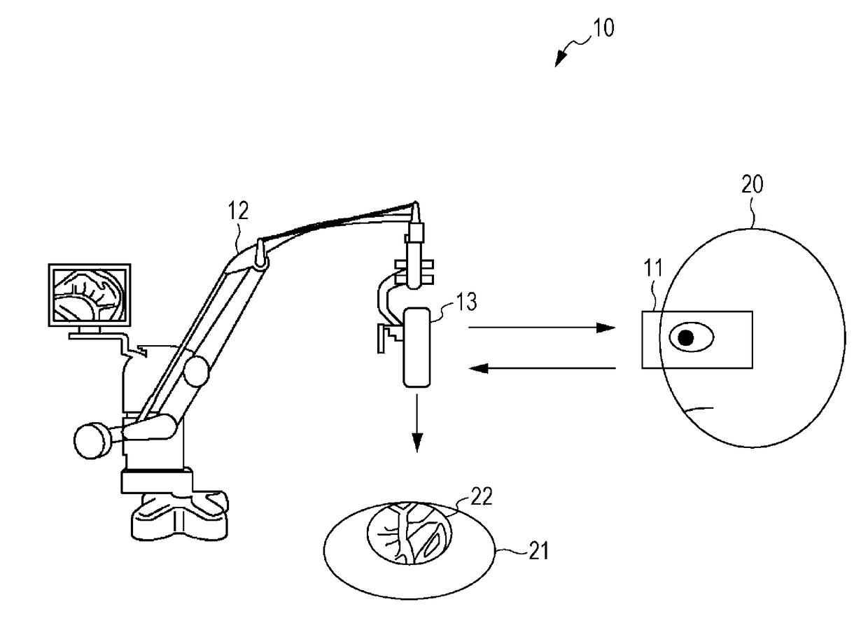
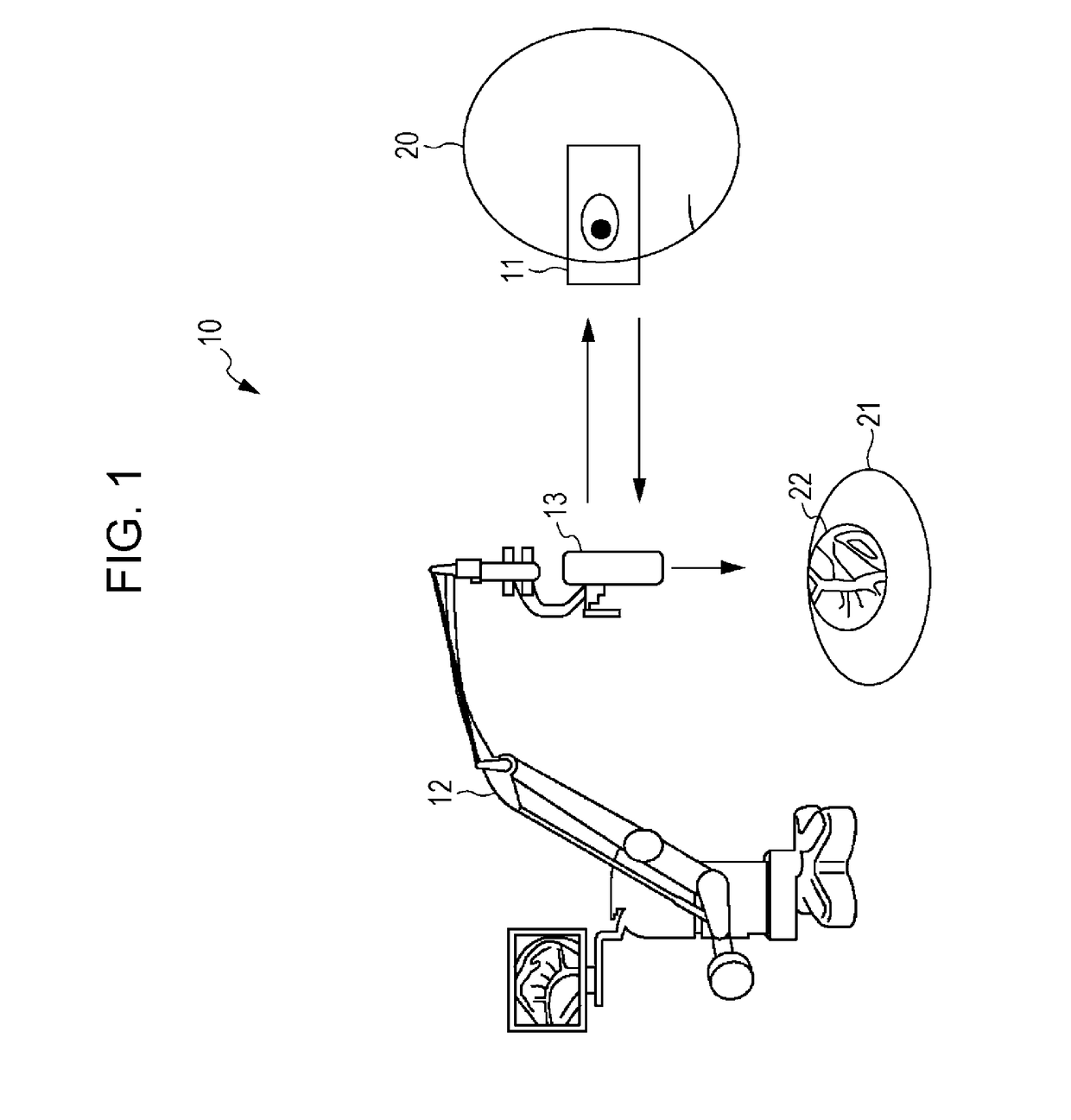
[0037]FIG. 1 is a diagram explaining an overview of a medical observation system in a first embodiment as an imaging control system to which the present disclosure is applied.

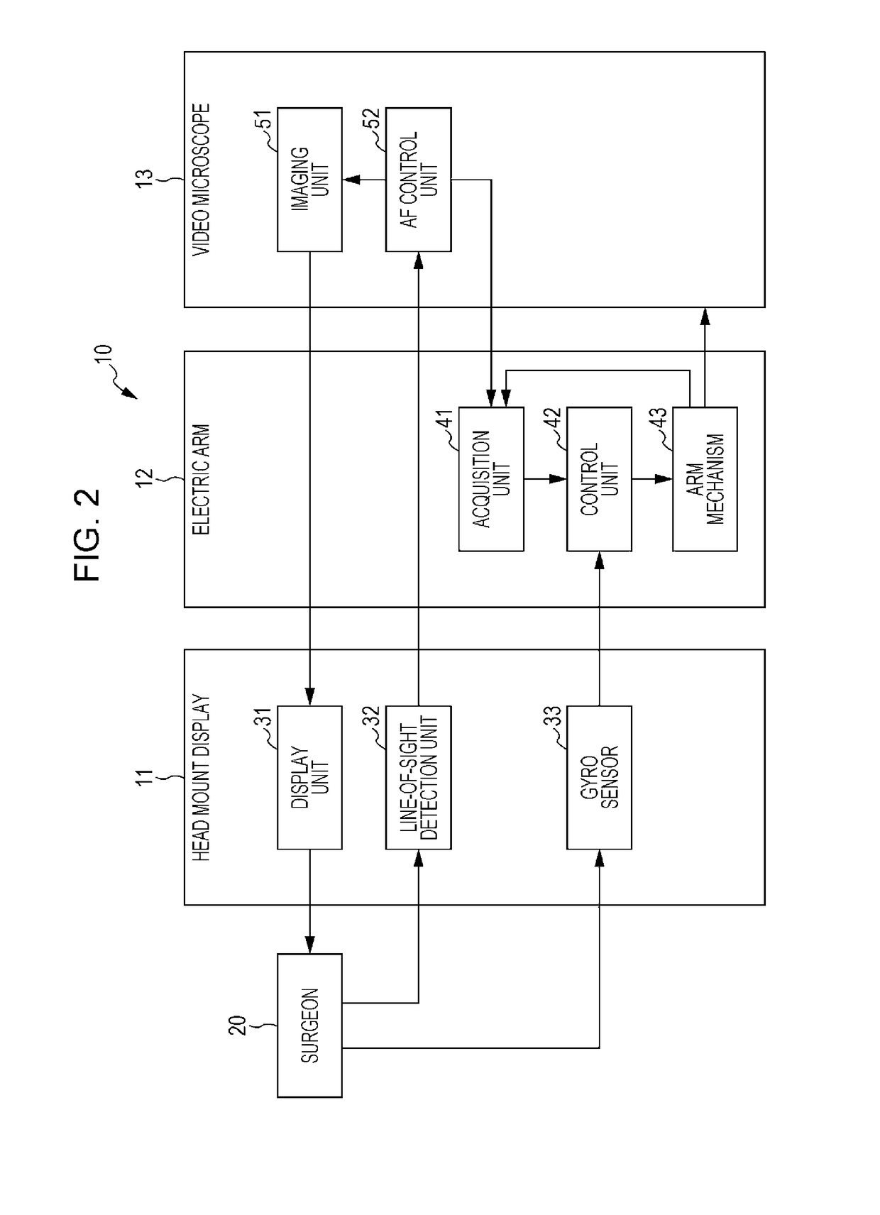
[0038]A medical observation system 10 is configured to include a head mount display 11, an electric arm 12, and a video microscope 13. A surgeon 20 as a user changes an imaging angle of the video microscope 13 by wearing the head mount display 11, looking at an image imaged by the video microscope 13 for surgical operation and displayed on the head mount display 11, and tilting the head vertically or horizontally.

[0039]Specifically, the head mount display 11 of the medical observation system 10 displays the image transmitted from the video microscope 13, in which an observation target 22 of a patient 21 is imaged as an object. At this time, the head mount display 11 detects a line-of-sight of the surgeon 20, and transmits gazing point position in...

second embodiment

[0131](Configuration Example of a Medical Observation System in a Second Embodiment

[0132]FIG. 11 is a block diagram illustrating a configuration example of a medical observation system in a second embodiment as an imaging control system to which the present disclosure is applied.

[0133]In the configuration illustrated in FIG. 11, the configuration the same as that in FIG. 2 will be referenced by the same reference signs. The duplicated descriptions will be appropriately omitted.

[0134]A medical observation system 100 in FIG. 11 is configured to include a head mount display 101, an electric arm 102, a video microscope 103, and a mode switching device 104. In the medical observation system 100, a control mode that controls the imaging angle and the focus area as operation modes can be set, and only in a case where the operation mode is the control mode, the imaging angle and the focus area is changed.

[0135]Specifically, a configuration of the head mount display 101 of the medical observ...

third embodiment

[0148](Configuration Example of a Medical Observation System in a Third Embodiment)

[0149]FIG. 12 is a block diagram illustrating a configuration example of a medical observation system in a third embodiment as an imaging control system to which the present disclosure is applied.

[0150]In the configuration illustrated in FIG. 12, the configurations the same as those in FIG. 2 and FIG. 11 will be referenced by the same reference signs. The duplicated descriptions will be appropriately omitted.

[0151]A configuration of a medical observation system 200 in FIG. 12 is different from that of the configuration of a medical observation system 100 in FIG. 11 in the point that a head mount display 201 is provided instead of the head mount display 101 and the video microscope 202 is provided instead of the video microscope 103. The medical observation system 200 changes the imaging magnification of the video microscope 202 according to the horizontal inclination of the head of the surgeon 20.

[015...


PUM


Abstract

A surgical control device that includes circuitry that changes an imaging viewpoint of a surgical imaging device in order to maintain a substantially constant distance between a focal point of an object and the surgical imaging device that images the object, based on a first instruction of a user and position information acquired by an acquisition unit implemented by circuitry configured to acquire position information indicating a position of the focal point of the object.

Description

TECHNICAL FIELD[0001]The present disclosure relates to a surgical control device, a control method, and an imaging control system, and particularly to a surgical control device, a control method, and an imaging control system by which a focused image with an imaging angle intended by a surgeon can be obtained.CROSS REFERENCE TO RELATED APPLICATIONS[0002]This application claims the benefit of Japanese Priority Patent Application JP 2014-071169 filed on Mar. 31, 2014, the entire contents of which are incorporated herein by reference.BACKGROUND ART[0003]In recent years, a medical observation system has been proposed, in which a point locking point is set independently from the setting of a focus position based on the measured data of the three dimensional shape of a portion to be observed (refer to PTL 1).[0004]In addition, in a general surgical endoscopic observation, an endoscopist other than a surgeon moves the position of an endoscope in order to obtain a focused image of an observ...

Claims


Application Information

Patent Timeline
Patent Type & Authority Applications(United States)
IPC IPC(8): G02B21/00G06F3/01G02B21/02A61B90/25G02B21/36
CPCG02B21/0012A61B90/25G02B21/365A61B90/50G06F3/013A61B2090/502G02B21/025A61B1/00149A61B1/00188A61B2034/2048A61B2090/368
Inventor HIRAYAMA, TOMOYUKI
Owner SONY CORP
Why Eureka
Try Eureka