
Spring Loading Insert

Inactive Publication Date: 2017-03-16
BAIRD HUGH PRESCOTT
View PDF0 Cites 2 Cited by
  • Summary
  • Abstract
  • Description
  • Claims
  • Application Information

AI Technical Summary

Benefits of technology

The present invention provides a spring loading insert for a tool holder, which can be used for various purposes such as engine turning, burnishing, and etching metal. This insert can be easily installed and removed without damaging the tool holder. The spring helps to prevent the tool from breaking or going into the material too quickly, providing a safe and effective way to spring load the tool. Overall, this invention provides a versatile, affordable, and safe way to spring load tools.

Problems solved by technology

Which due to the abrasive tool wearing down, and uneven surfaces is difficult to archive with a rigidly fixed tool, with a fixed z depth, or when trying to approximate abrasive tool wear and trying to program z depth changes accordingly, or when using a manual mill and trying to pull down on the z axes handle evenly every time.

Method used


Image

  • Spring Loading Insert
  • Spring Loading Insert
  • Spring Loading Insert

Examples


Embodiment Construction

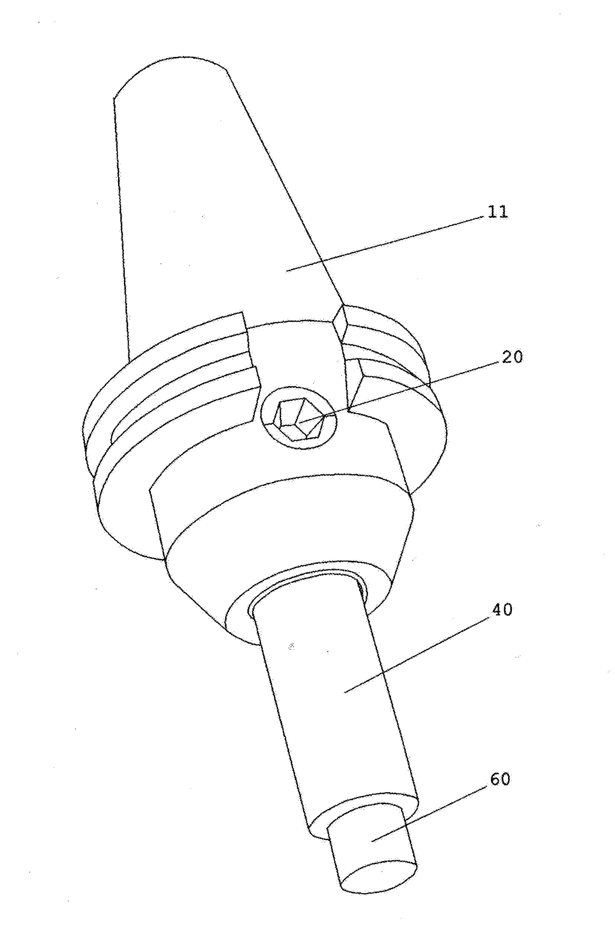
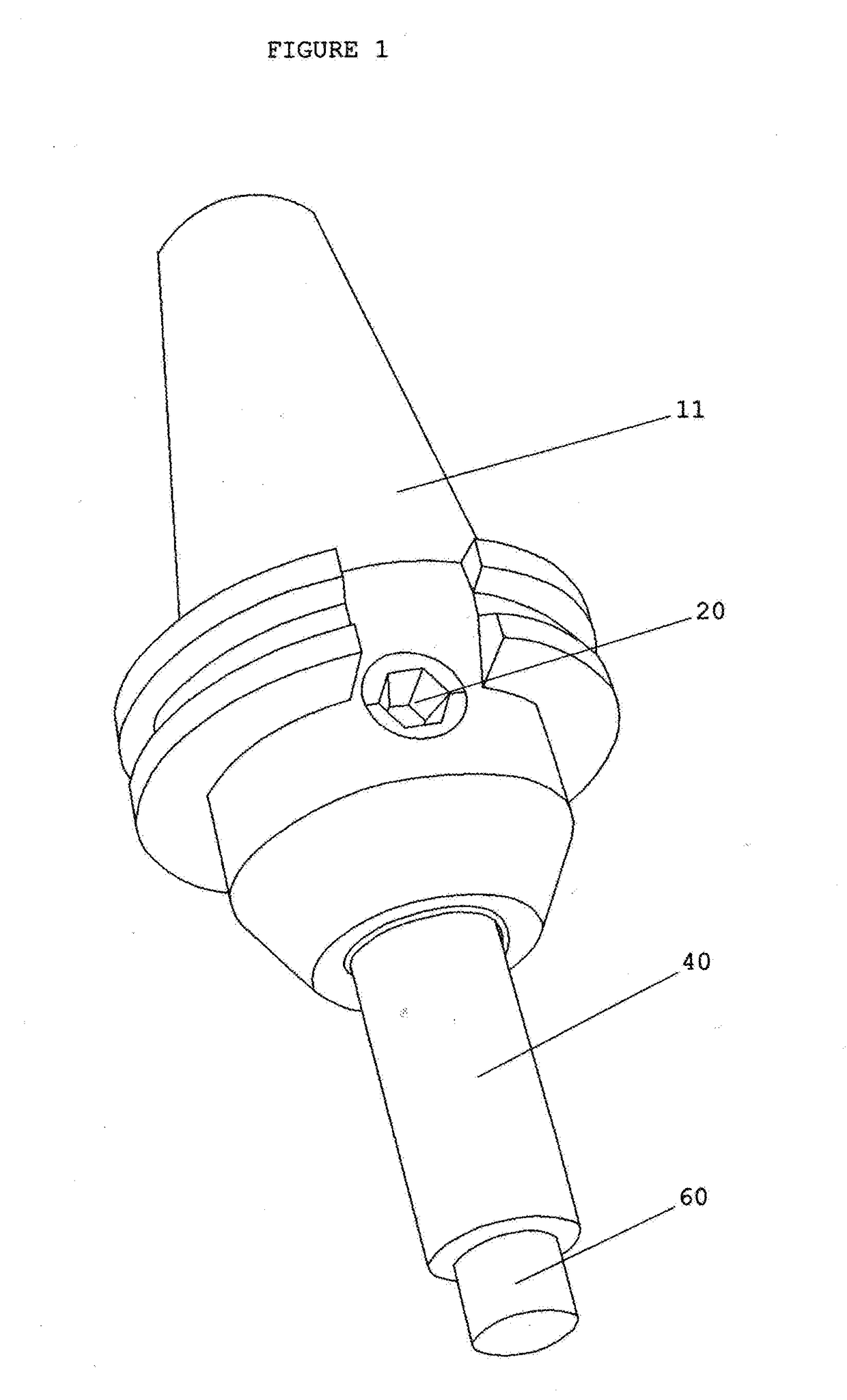
[0015]FIG. 1 is a embodiment of the invention with tool 60 installed and assembled into tool holder 11

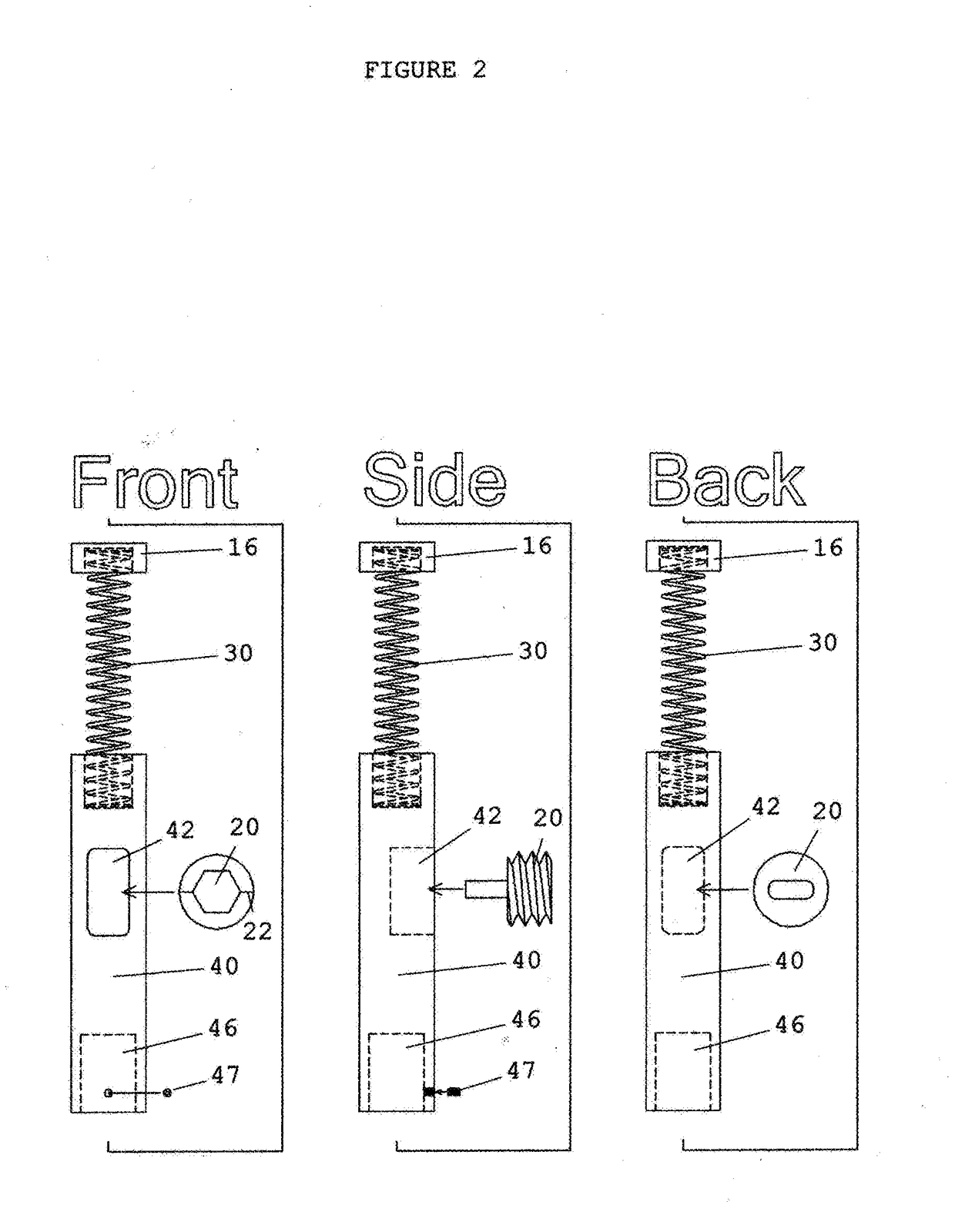
[0016]FIG. 2 is a front, side and back detail view of an embodiment of the invention, utilizing a compression spring 30 of varying size and rebound rates depending upon the tool 60 that will be used, and the outward pressure desired.

[0017]The insert 40 is machined from a phenolic rod because of it's strength, wear resistance, and slippery nature, but can also be manufactured using materials such as oil filled bearing bronze, aluminum, wood, plastic, or other material that is softer than the steel that the tool holder 11 is made of, so as not to cause undo wear to the tool holder tool pocket 62.

[0018]The end of the set screw 20 utilizes a oblong tab that has been machined on the one end that protrudes into the insert set screw pocket 42 and controls the in and out travel of the insert 40.

[0019]The oblong tab on the end of the set screw 20 is the preferred method of retention of inser...


PUM


Abstract

Spring loading insert comprising an insert, spring, and set screw or sleeve and snap ring for retention into a tool holder, which when installed into a tool holder, uses the tool holder tool pocket as the outer shell of the tool, making the tool holder part of the tool itself. By doing this and by having a wide verity of choices of outside diameters for the insert and not only tool pocket diameters but tool connection methods make this a vary versatile and inexpensive way to spring load a tool.

Description

FIELD OF THE INVENTION[0001]The present invention relates to C.N.C. and manual milling machines and, more particularly, to tool holders.BACKGROUND OF THE INVENTION[0002]Engine turning is a form of metal decorating where a fine geometric or repeating pattern is inscribed onto metal as a finish treatment, often consisting of hundreds if not thousands of overlapping circular swirls. To achieve a consistent result in the appearance, depth, and size of the swirls requires constant pressure of an abrasive tool on the surface of the metal. Which due to the abrasive tool wearing down, and uneven surfaces is difficult to archive with a rigidly fixed tool, with a fixed z depth, or when trying to approximate abrasive tool wear and trying to program z depth changes accordingly, or when using a manual mill and trying to pull down on the z axes handle evenly every time. By using a spring loading insert and by setting the z below the actual surface of the material the spring can deliver consistent...

Claims


Application Information

Patent Timeline
IPC IPC(8): B23B31/08
CPCB23B31/083B23B2231/22B23B2231/04B23B2260/136
Inventor BAIRD, HUGH PRESCOTT
Owner BAIRD HUGH PRESCOTT
Learn More