Vehicular storage unit

a vehicular storage unit and storage unit technology, applied in the direction of passenger space, etc., can solve the problems of limited degree of freedom of lid shape and opening, thereby the vehicular storage unit, and the detriment to the external styling appearance, so as to reduce the width direction dimension of the lid, increase the width direction dimension, suppress gaps

Active Publication Date: 2017-03-16
TOYOTA JIDOSHA KK
View PDF1 Cites 2 Cited by
  • Summary
  • Abstract
  • Description
  • Claims
  • Application Information

AI Technical Summary

Benefits of technology

[0011]In the second aspect, the width changing mechanism is provided to the lid. Slide members that project out toward the side walls are attached to the base member of the width changing mechanism. Each slide member has an end portion inserted inside the respective rail section, and is capable of moving along the opening width direction of the opening so as to follow the rail section. The pair of rail sections are formed to the side walls that are disposed facing each other on either side across the opening, such that the rail sections extend so as to separate from each other along the opening width direction of the opening. Thus, when the lid is moved along the length direction of the storage unit main body in the direction in which the opening width of the opening increases, the slide members move toward the opening width direction outsides of the opening, and the first supporting members that are supported by the slide members also move toward the opening width direction outsides of the opening when this occurs. At the same time, the second supporting members that are supported by the slide members through the first coupling members also move toward the vehicle width direction outsides of the opening. When this occurs, since the second coupling members are attached to the respective second supporting members further toward the vehicle lower side than the pivot centers of the second supporting members, the second supporting members pivot from the opening upper side toward the opening width direction outsides as viewed along the length direction of the storage unit main body. The first supporting members, which are interlocked so as to pivot in the opposite direction to the respective second supporting members, pivot from the opening upper side toward the lid width direction inside. This pivoting of the first supporting members enables the width direction dimension of the lid to be increased, while stretching the styling section, attached to the circular arc portions of the first supporting members, along the lid width direction. This enables gaps to be suppressed from occurring between the opening and the lid at the location where the opening increases in the opening width direction.
[0012]When the lid is moved along the length direction of the storage unit main body in the direction in which the opening width of the opening decreases, the slide members move toward the opening width direction inside of the opening so as to follow the opening width of the opening, and the first supporting members that are supported by the slide members also move toward the opening width direction inside of the opening when this occurs. At the same time, the second supporting members that are supported by the slide members through the first coupling members also move toward the vehicle width direction inside of the opening. When this occurs, since the second coupling members are attached to the respective second supporting members further toward the vehicle lower side than the pivot centers of the second supporting members, the second supporting members pivot from the opening upper side toward the lid width direction inside as viewed along the length direction of the storage unit main body. The first supporting members, which are interlocked so as to pivot in the opposite direction to the respective second supporting members, pivot from the opening upper side toward the lid width direction outsides. This pivoting of the first supporting members enables the width direction dimension of the lid to be decreased, while the styling section, attached to the circular arc portions of the first supporting members, is wound onto an inner portion of the lid, and compressed along the lid width direction. This suppresses the lid from becoming unable to slide at the location of the opening where the opening width decreases. This enables the width direction dimension of the lid to be made to follow the spacing between the pair of rail sections provided to the opening, thereby enabling the opening width of the opening, and therefore the vehicle width direction dimension of the vehicular storage unit to be freely set to suit peripheral components.

Problems solved by technology

The slide shafts projecting out at either vehicle width direction end portion of the lid slide along the guide grooves formed to the box, such that, when configuration is such that the opening width of the opening increases from a specific position, gaps occur between the lid and the opening when the lid is made to slid along the guide grooves, which is detrimental to the external styling appearance.
The shape of the lid and the shape of the opening that is opened or closed by the lid need to be shapes that have a uniform vehicle width direction dimension, such that the degrees of freedom for the shape of the lid and the opening, and thereby the vehicular storage unit, are limited.

Method used


Image

  • Vehicular storage unit
  • Vehicular storage unit
  • Vehicular storage unit

Examples


first exemplary embodiment

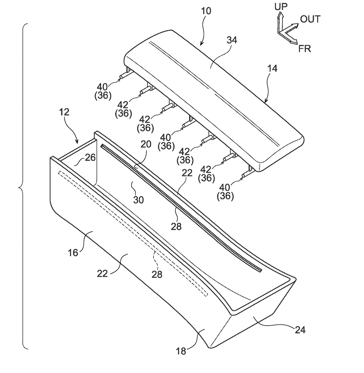
[0022]Explanation follows regarding an exemplary embodiment of a vehicular storage unit according to the present disclosure, with reference to FIGS. 1 to 3. Note that in each of the drawings, the arrow FR indicates the vehicle front-rear direction front side, the arrow OUT indicates the vehicle width direction outside, and the arrow UP indicates the vehicle up-down direction upper side.

[0023]As illustrated in FIG. 1, a vehicular storage unit 10 includes a storage unit main body 12, and a lid 14. The storage unit main body 12 is formed in an elongated box shape with its length direction along the vehicle front-rear direction. The storage unit main body 12 is disposed between a driving seat and a front passenger seat, and is configured by a general section 16 with a vehicle width direction dimension that is set to suit the location of the narrowest spacing between the driving seat and the front passenger seat, and a widened section 18 that is disposed further toward the vehicle front ...

second exemplary embodiment

[0047]Explanation follows regarding a vehicular storage unit according to a second exemplary embodiment of the present invention, with reference to FIG. 5. Note that similar configuration portions to the first exemplary embodiment described above are appended with the same reference numerals, and explanation thereof is omitted.

[0048]As illustrated in FIG. 5, a vehicular storage unit 96 according to the second exemplary embodiment has basically the same configuration as that in the first exemplary embodiment, with the exception that a dependent section 102 is formed to each slide member 100 of a lid 98.

[0049]Namely, rail sections 104 are formed to the side walls 22 of the storage unit main body 12. The rail sections 104 extend along substantially the vehicle front-rear direction at the side faces 30 at the vehicle width direction inside of the side walls 22, and are each configured including a substantially L-shaped space formed by a pair of rail side walls 105 extending along the ve...

third exemplary embodiment

[0055]Explanation follows regarding a vehicular storage unit according to a third exemplary embodiment of the present invention, with reference to FIG. 6. Note that similar configuration portions to the first exemplary embodiment previously described are appended with the same reference numerals, and explanation thereof is omitted.

[0056]As illustrated in FIG. 6, a vehicular storage unit 110 according to the third exemplary embodiment has basically the same configuration as that in the first exemplary embodiment, with the exception that each second supporting member 52 of a lid 113 is attached to a base member 112 through a second coupling member 111 so as to be capable of pivoting.

[0057]Namely, the base member 112 is formed in a substantially rectangular plate shape with a vehicle width direction dimension of a size that is set smaller than the opening width of the opening 20, and is disposed inside the opening 20. A base extension section 114 is formed extending toward the vehicle ...


PUM


Abstract

A vehicular storage unit that includes: an elongated shaped storage unit main body that is formed with an opening open toward a vehicle cabin inner side; and a lid that is provided at the vehicle cabin inner side of the opening, and that is supported by the storage unit main body so as to be capable of moving along a length direction of the storage unit main body. An opening width of the opening increases from a specific position on progression from one side toward another side of the storage unit main body in a length direction, and a width of the lid is increased so as to follow the opening width of the opening.

Description

CROSS-REFERENCE TO RELATED APPLICATION[0001]This application is based on and claims priority under 35 USC 119 from Japanese Patent Application No. 2015-179950 filed on Sep. 11, 2015, which is incorporated by reference herein.BACKGROUND[0002]Technical Field[0003]The present invention relates to a vehicular storage unit.[0004]Related Art[0005]Japanese Patent Application Laid-Open (JP-A) No. 2013-28240 describes a vehicular storage unit. Specifically, the vehicular storage unit includes a box that is disposed between a driving seat and a front passenger seat and includes an opening at an upper face thereof, and a lid that opens or closes the opening of the box. Plural hinges that are thin along the vehicle width direction are formed to the lid at spacings along the vehicle front-rear direction. The lid is thereby capable of elastic deformation along the vehicle front-rear direction. Plural slide shafts project out toward the vehicle width direction outsides at either vehicle width dire...

Claims


Application Information

Patent Timeline
Patent Type & Authority Applications(United States)
IPC IPC(8): B60R7/04
CPCB60R7/04
Inventor KARIYA, YUJI
Owner TOYOTA JIDOSHA KK
Why Eureka
Try Eureka