
Method, system, and executable program product for controlling lighting

a technology of executable program products and methods, applied in the direction of general lighting, mass transit vehicle lighting, aircraft crew accommodation, etc., can solve the problem of no prior art system that combined

Active Publication Date: 2017-03-16
BOMBARDIER INC
View PDF9 Cites 18 Cited by
  • Summary
  • Abstract
  • Description
  • Claims
  • Application Information

AI Technical Summary

Benefits of technology

The present invention provides a lighting control system that can sense and control the position, configuration, and movement of a passenger's hands, as well as the position of the seat and the direction of movement of the passenger's hands. The system includes a sensor that can generate a signal based on the position, configuration, and movement of the passenger's hands, and a controller that can adjust various parameters such as light intensity, color, projected pattern, and width based on the sensor's signal. The system can also include a passenger input device for adjusting various parameters. The technical effects of the invention include improved control over the lighting system and improved passenger comfort and safety.

Problems solved by technology

There are no prior art systems that combine controls over two or more of comfort features including overhead lighting, cabin lighting, the degree of openness of window shades, the direction of the air nozzles within the aircraft cabin, and the flow rate through the air nozzles.

Method used


Image

  • Method, system, and executable program product for controlling lighting
  • Method, system, and executable program product for controlling lighting
  • Method, system, and executable program product for controlling lighting

Examples


second embodiment

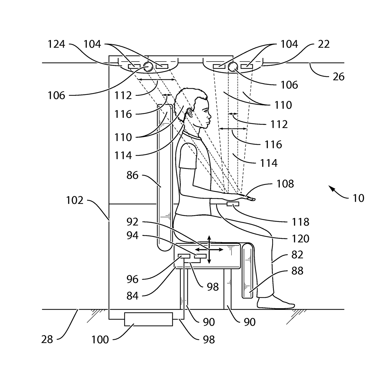
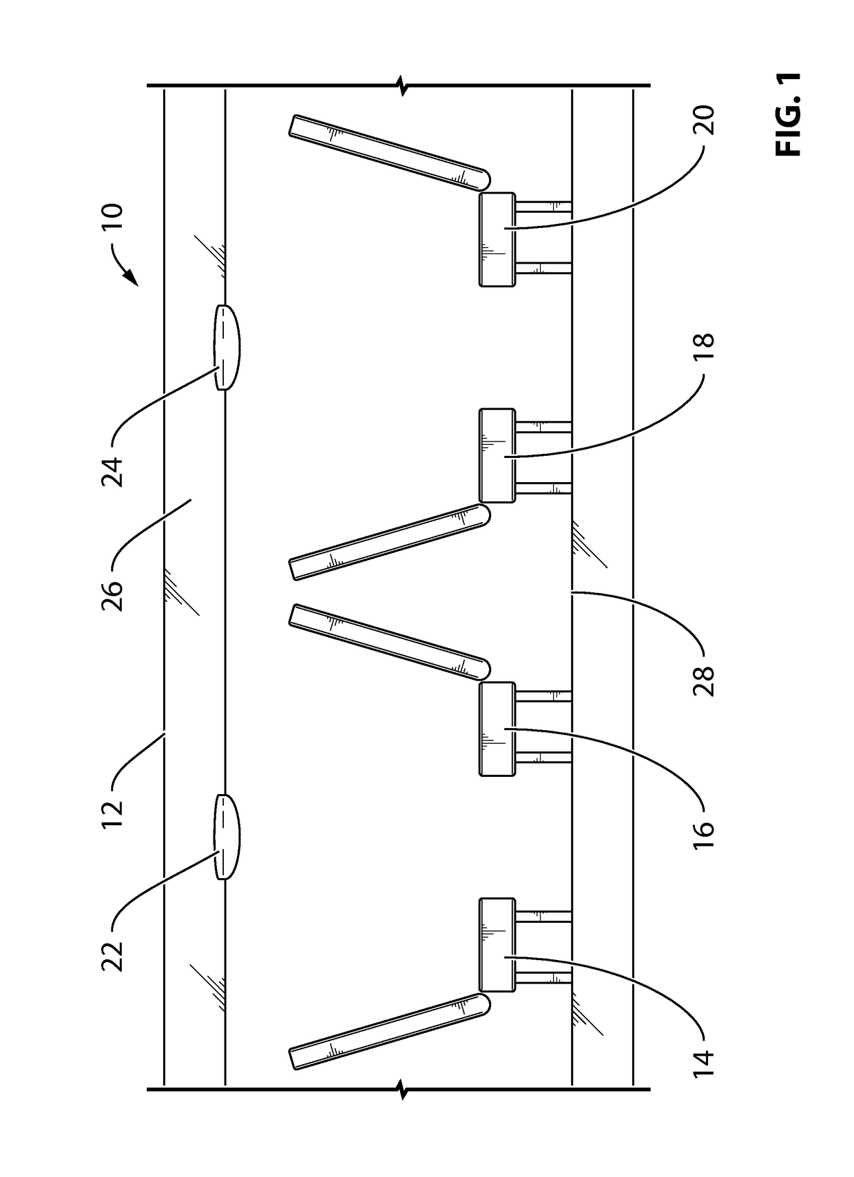
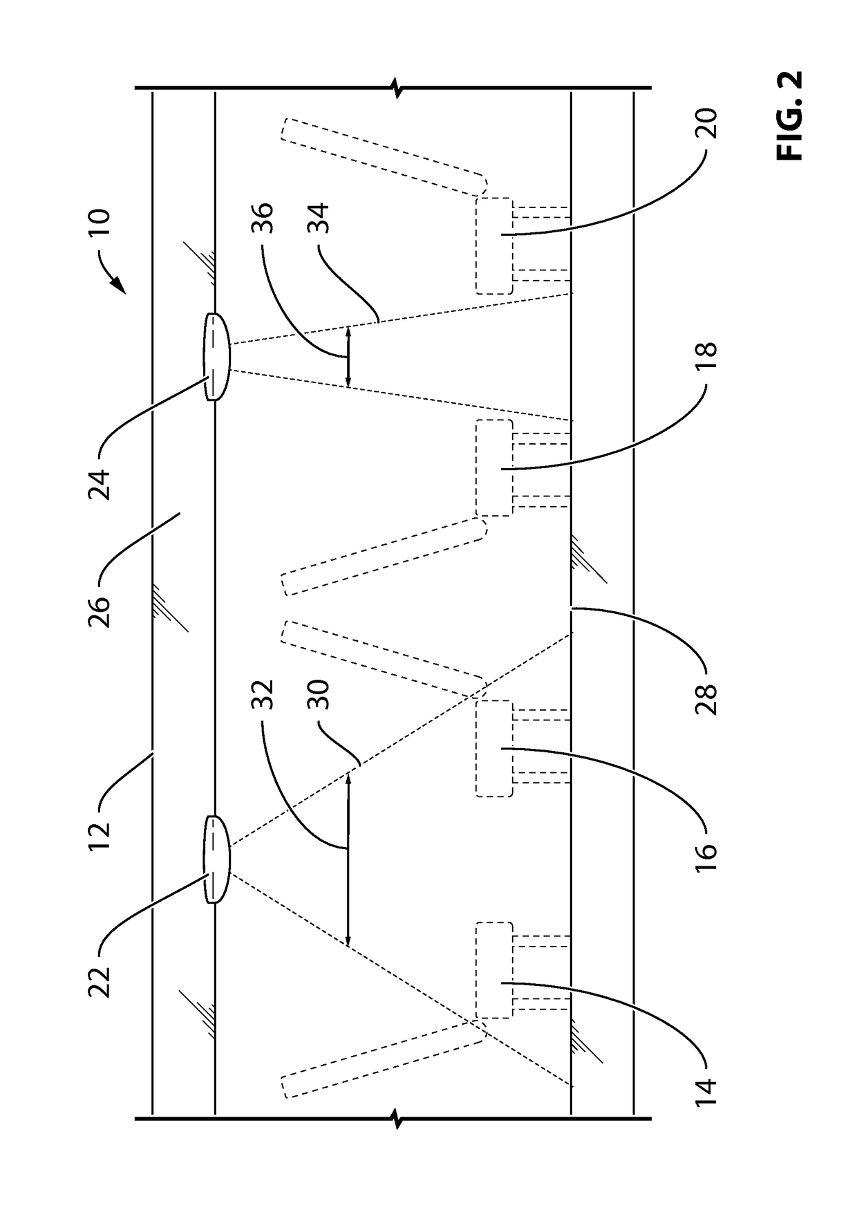
[0125]FIG. 9 is a graphical side view of a single seat as may be used in connection with the lighting system 122. As in FIG. 6, the seat 14 is shown in an upright orientation (otherwise referred to as the TTL orientation).

[0126]The lighting system 122 is similar to the lighting system 10 illustrated in FIGS. 6-8. However, in the lighting system 122, a second light fixture 124 is disposed on the overhead storage area 26 above the seat 14.

[0127]It is noted that the light fixture 124 is contemplated to be identical to the light fixture 22. However, the light fixture 124 need not be the same as the light fixture 22. To the contrary, the light fixtures 22, 124 may differ in construction and operation from one another without departing from the scope of the present invention.

[0128]As with the light fixture 22, the light fixture 124 may or may not include a light source 106 and one or more third sensors (or hand sensors) 104. Similar to the light fixture 22, the light fixture 124 generates...

first embodiment

[0133]FIG. 13 illustrates a second contemplated relationship between the hand sensing column 110 and the light column 114. This second contemplated relationship is a variation of the first embodiment that is shown in FIG. 12. Here, the hand sensing column 110 encompasses the light column 114 only in part. As such, the lighting area is dissociated from the location of the hands 108 of the passenger 82. The orientation illustrated in FIG. 13 may be applied in instances where, for example, the light column 114 is incapable of providing illumination in a particular area of the cabin 12 of the aircraft.

[0134]FIGS. 12 and 13 illustrate two possible relationships between the hand sensing column 110 and the light column 114. In both cases, consistent with the present invention, it is contemplated that the hand sensing column 110 overlaps, at least in part, the light column 114. It is noted that there may be instances where the hand sensing column 110 and the light column 114 do not overlap....

third embodiment

[0185]FIG. 18 illustrates an embodiment of a passenger service system 148. The passenger service system 148 provides control for passenger services, including lighting. As will be made apparent from the discussion that follows, the passenger service system 148 provides functionality in addition to the functionality made available by the lighting systems 10, 122 described above.

[0186]The passenger service system 148 is contemplated to include many of the features described in connection with the lighting system 122. In this embodiment of the passenger service system 148, the controller 100 receives input in addition to that received by the lighting system 122 and provides additional control signals to refine management of several comfort-related parameters within the cabin 12 of the aircraft.

[0187]As illustrated in FIG. 18, the cabin 12 includes at least one window 150 with a window shade 152. The window 150 is positioned adjacent to the seat 14, as might be expected for a typical la...


PUM


Abstract

A lighting control system includes a sensor to generate a signal representative of at least one of a position of a seat, a presence of passenger in the seat, the position of at least one hand of the passenger, a configuration of the at least one hand of the passenger, and a direction of movement of the at least one hand of the passenger. A first light source, which generates a first light column, is located forward of the seat. A second light source, which generates a second light column, is located rearward of the seat. A controller generates a control signal that controls at least one parameter associated with an intensity, a color, a projected pattern, projected pattern location, or a width formed by a combination of the first and second light columns.

Description

CROSS-REFERENCE TO RELATED APPLICATION(S)[0001]This International Patent Application claims priority to U.S. Provisional Patent Application Ser. No. 61 / 946,244, filed Feb. 28, 2014.FIELD OF THE INVENTION[0002]The present invention concerns an apparatus, method, and system for providing and controlling passenger services, such as overhead lighting units in the cabin of a vehicle. More specifically, the present invention concerns an apparatus, method, and system for providing and controlling overhead lighting units, and other comfort features, in the vehicle cabin.DESCRIPTION OF THE RELATED ART[0003]As should be apparent to any air traveler, overhead lighting is standard in any aircraft. In passenger aircraft, the overhead light (also referred to as a “reading light”) may be actuated by pressing an on-off switch near to the overhead light. In still another well-known example, the passenger may activate the overhead light via an on-off switch, such as a switch on an armrest of the seat...

Claims


Application Information

Patent Timeline
Patent Type & Authority Applications(United States)
IPC IPC(8): B64D11/00B60Q3/02H05B33/08H05B37/02H05B44/00
CPCB64D11/00H05B37/0227B60Q3/0259H05B33/0854B64D2011/0053H05B37/0218B60Q3/0253B64D2203/00H05B33/0872B64D2011/0038H05B47/105B64C1/1484B64D2013/003B60Q3/43B60Q3/47B60Q3/44Y02B20/40H05B47/115H05B45/20H05B45/12H05B47/11
Inventor GAGNON, PIERREREZILE, JOSEPHKIRMOYAN, MARCNOLEN, BRADLACHERE, JULIEN FABRICEKARCESKI, JEFFREY DAVID
Owner BOMBARDIER INC
Learn More