Engine cooling system

a cooling system and engine technology, applied in the direction of engine cooling apparatus, machines/engines, mechanical equipment, etc., to achieve the effect of preventing an excessive increase in coolant pressure, and reducing the pressure increas

Inactive Publication Date: 2017-03-16
TOYOTA JIDOSHA KK
View PDF15 Cites 18 Cited by
  • Summary
  • Abstract
  • Description
  • Claims
  • Application Information

AI Technical Summary

Benefits of technology

[0009]With the thus configured engine cooling system, even when flow of coolant stagnates at the multi-way valve and the pressure of coolant at a portion upstream of the multi-way valve increases, it is possible to relieve the increased pressure by opening the relief valve to let coolant to escape from a portion upstream of the multi-way valve to a portion downstream of the multi-way valve through the relief route. However, if coolant that has passed through the relief route is configured to flow into the radiator, coolant constantly flows into the radiator through the relief route when the relief valve is stuck open, so there is a concern that the engine is cooled more than necessary. In terms of this point, with the engine cooling system, the relief destination of the relief route is set to a portion downstream of the multi-way valve and upstream of the pump in the coolant circuit and other than a portion upstream of the radiator in the radiator route. For this reason, even when the relief valve is stuck open, coolant does not constantly flow into the radiator, and excessive cooling of the engine due to the constant flow of coolant into the radiator also does not occur. That is, with the engine cooling system, an excessive increase in coolant pressure at a portion upstream of the multi-way valve is prevented, and the engine is not excessively cooled even when the relief valve installed for the purpose of preventing an excessive increase in coolant pressure is stuck open. Therefore, with the engine cooling system, it is possible to suitably prevent an excessive increase in coolant pressure.

Problems solved by technology

However, if coolant that has passed through the relief route is configured to flow into the radiator, coolant constantly flows into the radiator through the relief route when the relief valve is stuck open, so there is a concern that the engine is cooled more than necessary.

Method used


Image

  • Engine cooling system
  • Engine cooling system
  • Engine cooling system

Examples


first embodiment

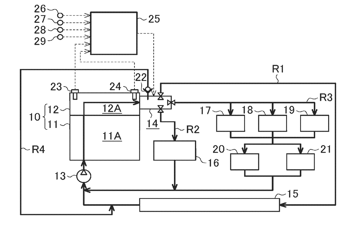
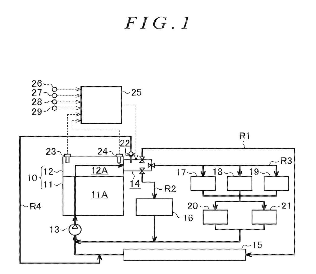
[0020]Hereinafter, an engine cooling system will be described in detail with reference to FIG. 1 to FIG. 6. Initially, the configuration of a coolant circuit through which coolant for cooling an engine flows in the engine cooling system according to the present embodiment will be described with reference to FIG. 1.

[0021]As shown in FIG. 1, water jackets 11A, 12A, which are part of the coolant circuit, are respectively provided in a cylinder block 11 and cylinder head 12 of the engine 10. A coolant pump 13 for circulating coolant through the coolant circuit is provided at a portion upstream of the water jackets 11A, 12A in the coolant circuit. A mechanical pump that is driven by power transmitted from the engine 10 is employed as the coolant pump 13. Coolant discharged from the coolant pump 13 is introduced into the water jackets 11A, 12A.

[0022]An inlet coolant temperature sensor 23 is provided in the water jacket 12A of the cylinder head 12. The inlet coolant temperature sensor 23 d...

second embodiment

[0052]Next, the engine cooling system will be described in detail additionally with reference to FIG. 7. In the present embodiment, like reference numerals denote components common to those of the above-described embodiment, and the detailed description thereof is omitted.

[0053]In the first embodiment, the relief destination of the relief route R4 is set to the portion downstream of the radiator 15 in the radiator route R1. Of course, even when the relief destination of the relief route R4 is set to any position as long as the portion is located downstream of the multi-way valve 14 and upstream of the coolant pump13 in the coolant circuit and is other than a portion upstream of the radiator 15 in the radiator route R1, it is possible to achieve the purpose of preventing excessive cooling of the engine 10 at the time when the relief valve 22 is stuck open.

[0054]As shown in FIG. 7, in the engine cooling system according to the present embodiment, the relief route R4 is provided so as ...


PUM


Abstract

An engine cooling system includes a coolant circuit, a multi-way valve, a relief route and a relief valve. The coolant circuit includes a first route and a second route into which the coolant circuit is branched off at a branched position. The first route passes through a radiator. The multi-way valve is provided at the branched position. The relief route sets a relief source to a portion downstream of a pump and upstream of the multi-way valve in the coolant circuit, sets a relief destination to a portion downstream of the radiator in the first route, and causes coolant to flow from the relief source to the relief destination so as to bypass the multi-way valve. The relief valve interrupts circulation of coolant through the relief route when the relief valve is closed, and permits circulation of coolant through the relief route when the relief valve is open.

Description

INCORPORATION BY REFERENCE[0001]The disclosure of Japanese Patent Application No 2015-183239 filed on Sep. 16, 2015 including the specification, drawings and abstract is incorporated herein by reference in its entirety.BACKGROUND OF THE INVENTION[0002]1. Field of the Invention[0003]The invention relates to an engine cooling system that cools an engine by circulating coolant through the inside of the engine.[0004]2. Description of Related Art[0005]In a liquid-cooled engine, the engine is cooled by circulating coolant between the inside of the engine and a radiator with the use of a pump. Conventionally, as described in Japanese Patent Application Publication No. 2015-010577 (JP 2015-010577 A), there is such a cooling system for a liquid-cooled engine, in which a coolant circuit through which coolant is circulated branches off into a plurality of routes outside the engine, the plurality of routes including a radiator route that passes through a radiator, and a multi-way valve is provi...

Claims


Application Information

Patent Timeline
Patent Type & Authority Applications(United States)
IPC IPC(8): F01P7/16F01P5/10
CPCF01P7/165F01P2007/146F01P5/10
Inventor KANEKO, RIHITOTAKAGI, NOBORUTAKAGI, LSAOKAWAMOTO, NAOYAKIMURA, KENJIYUMI, SHINJI
Owner TOYOTA JIDOSHA KK
Why Eureka
Try Eureka