X-ray small angle optical system

a small angle, optical system technology, applied in the field of x-ray small angle optical system, can solve the problems of detectors becoming difficult to implement, the s/n ratio may become worse, and the movement limitation, etc., to achieve the desired angular resolution. the effect of easy operation

Active Publication Date: 2017-03-16
RIGAKU CORP
View PDF2 Cites 10 Cited by
  • Summary
  • Abstract
  • Description
  • Claims
  • Application Information

AI Technical Summary

Benefits of technology

[0018]According to the present invention, an X-ray small angle optical

Problems solved by technology

As a result, an S/N ratio may become worse.
However, there arise problems in that, when the gap between the sample S and the X-ray detector 3 is to

Method used


Image

  • X-ray small angle optical system
  • X-ray small angle optical system
  • X-ray small angle optical system

Examples


Embodiment Construction

[0029]Now, an embodiment of the present invention is described referring to the drawings. For clearer illustration, some sizes, shapes, and the like are schematically illustrated in the drawings in comparison to actual ones. However, the sizes, the shapes, and the like are merely an example, and do not limit understanding of the present invention. Further, like elements as those described relating to the drawings already referred to are denoted by like reference symbols herein and in each of the drawings, and detailed description thereof is sometimes omitted as appropriate.

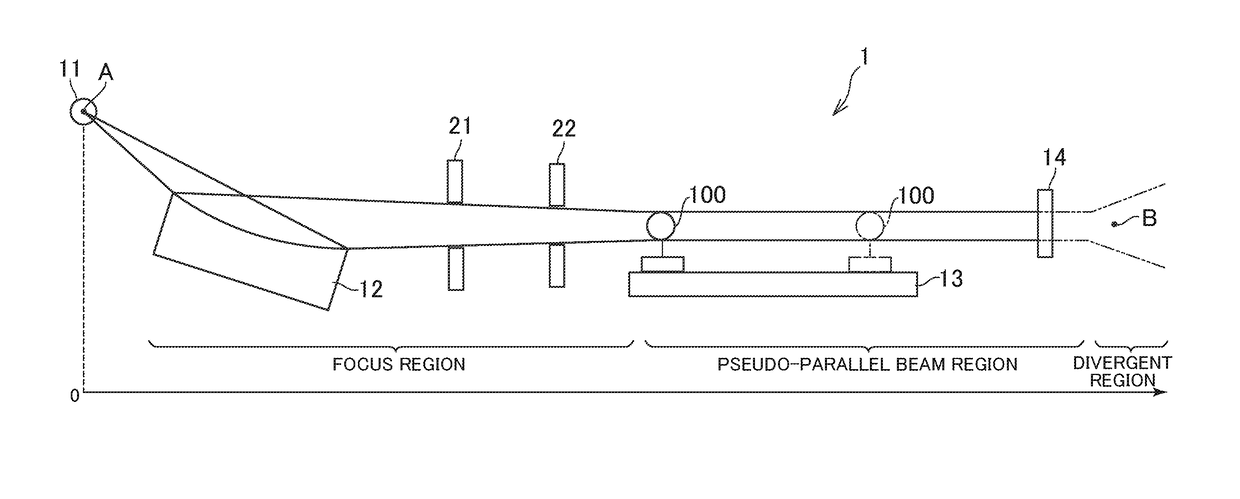
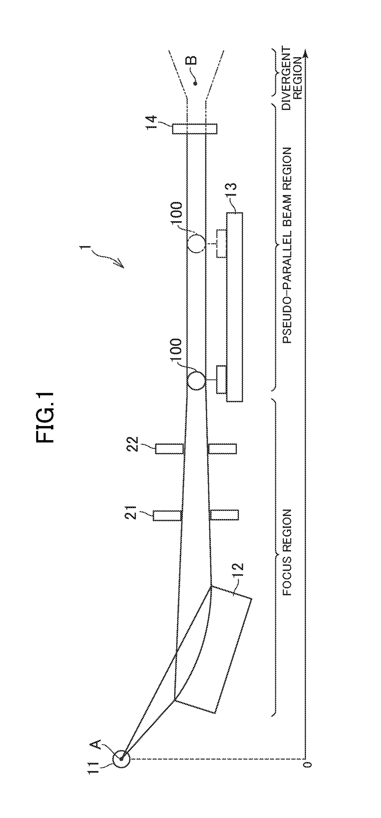
[0030]FIG. 1 is a schematic view for illustrating the structure of an X-ray small angle optical system 1 according to an embodiment of the present invention. The X-ray small angle optical system 1 according to this embodiment is an X-ray small angle scattering device used on a laboratory basis (that is, in a laboratory) for example. The X-ray small angle optical system 1 includes an X-ray source 11, a multilayer m...


PUM


Abstract

Provided is an X-ray small angle optical system, which easily achieves a desired angular resolution, including: an X-ray source having a microfocus; a multilayer mirror having an elliptical reflection surface, and being configured to collect X-rays emitted from the X-ray source and to irradiate a sample; and an X-ray detector configured to detect scattered X-rays generated from the sample, in which the elliptical reflection surface of the multilayer mirror has a focal point A and a focal point B, in which the X-ray source is arranged such that the microfocus includes the focal point A, and in which the X-ray detector is arranged on the multilayer mirror side of the focal point B.

Description

CROSS-REFERENCE TO RELATED APPLICATION[0001]The present application claims priority from Japanese application JP 2015-179651, filed on Sep. 11, 2015, the content of which is hereby incorporated by reference into this application.BACKGROUND OF THE INVENTION[0002]Field of the Invention[0003]The present invention relates to an X-ray small angle optical system.[0004]Description of the Related Art[0005]There has been used an X-ray small angle optical system, which is configured to collect X-rays emitted from an X-ray source by a focusing device. In U.S. Pa. No. 6,504,902, there is disclosed an X-ray optical device including a multilayer mirror having elliptical reflection surfaces. As illustrated in FIG. 1 of U.S. Pat. No. 6,504,902, a sample S is placed at a convergent point (focal point B) of X-rays reflected from a multilayer mirror 1, and an X-ray detector 3 is arranged downstream thereof. In other words, a region from the focusing device (multilayer mirror 1) to the sample is a focu...

Claims


Application Information

Patent Timeline
IPC IPC(8): G01N23/201
CPCG01N23/201G01N2223/315G01N2223/054G01N23/207
Inventor ITO, KAZUKIOMOTE, KAZUHIKOJIANG, LICAI
Owner RIGAKU CORP
Why Eureka
Try Eureka