A wearable 3D augmented reality display

Active Publication Date: 2017-03-16
UNIV OF CONNECTICUT +1
View PDF5 Cites 137 Cited by
  • Summary
  • Abstract
  • Description
  • Claims
  • Application Information

AI Technical Summary

Benefits of technology

[0007]In one of its aspects the present invention may provide a 3D augmented reality display having a microdisplay for providing a virtual 3D image for display to a user. For example, the optical approach of the present invention may uniquely combine the optical paths of an AR display system with that of a

Problems solved by technology

With the rapidly increased bandwidth of wireless networks, the miniaturization of electronics, and the prevailing cloud computing, one of the current challenges is to realize an unobtrusive AR display that integrates the functions of OST-HMDs, smart phones, and mobile computing within the volume of a pair of eyeglasses.
The lack of high-perf

Method used


Image

  • A wearable 3D augmented reality display
  • A wearable 3D augmented reality display
  • A wearable 3D augmented reality display

Examples


examples

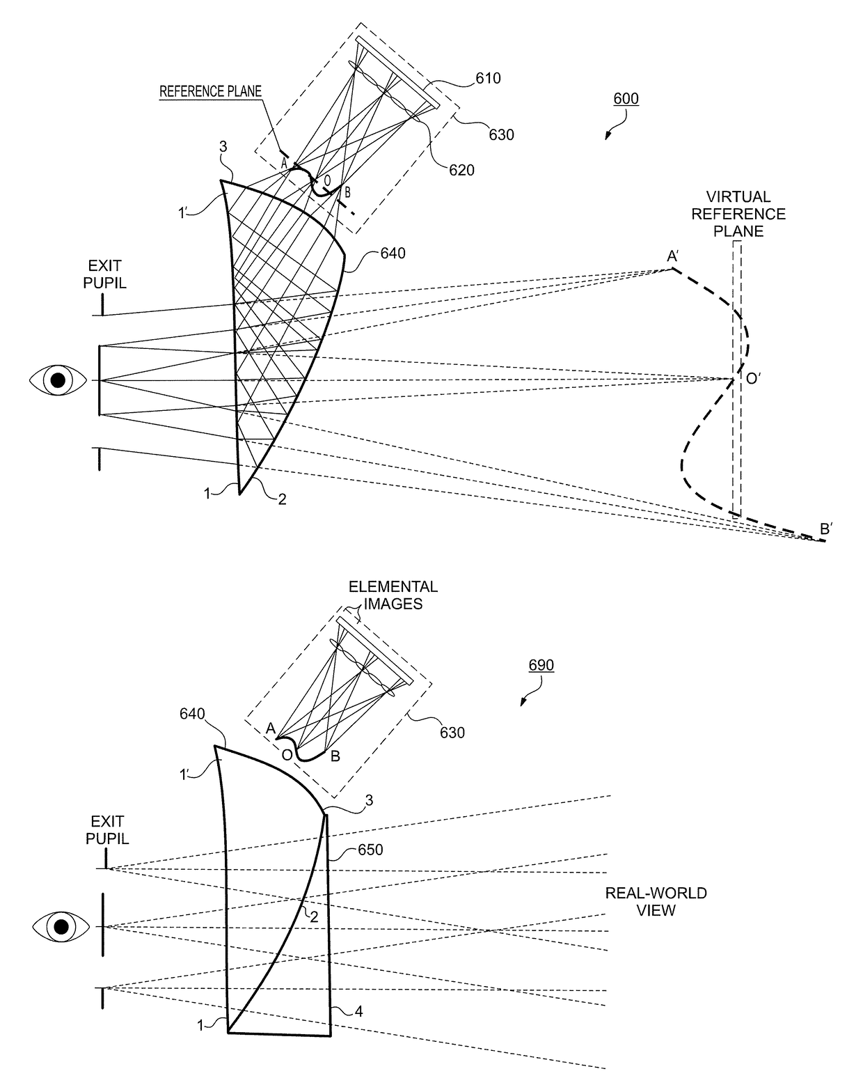
[0037]A proof-of-concept monocular prototype of an InI OST-HMD according to the configuration of FIG. 6C was implemented using off-the-shelf optical components, FIG. 8. A micro-lens array (MLA) of a 3.3 mm focal length and 0.985 mm pitch was utilized. (These types of microlenses can be purchased from Digital Optics Corp, SUSS Microoptics, etc.) The microdisplay was a 0.8″ organic light emitting display (OLED), which offered 1920×1200 color pixels with a pixel size of 9.6 μm. (EMA-100820, by eMagin Corp, Bellevue, Wash.) A freeform eyepiece along with a see-through corrector were used of the type disclosed in International Patent Application No. PCT / US2013 / 065422, the entire contents of which are incorporated herein by reference. The specifications of the eyepiece 640 and corrector 650 are provided in the tables below. The eyepiece offered a field of view of 40 degrees and approximately a 6.5 mm eyebox. Due to the strict telecentricity of the eyepiece design, it was adapted to the In...


PUM


Abstract

A wearable 3D augmented reality display and method, which may include 3D integral imaging optics.

Description

RELATED APPLICATIONS[0001]This application of claims the benefit of priority of U.S. Provisional Application No. 61 / 948,226, filed on Mar. 5, 2014, the entire contents of which application(s) are incorporated herein by reference.FIELD OF THE INVENTION[0002]The present invention relates generally to a wearable 3D augmented reality display, and more particularly, but not exclusively, to a wearable 3D augmented reality display comprising 3D integral imaging (InI) optics.BACKGROUND OF THE INVENTION[0003]An augmented reality (AR) display, which allows overlaying 2D or 3D digital information on a person's real-world view, has long been portrayed as a transformative technology to redefine the way we perceive and interact with digital information. Although several types of AR display devices have been explored, a desired form of AR displays is a lightweight optical see-through head-mounted display (OST-HMD), which enables optical superposition of digital information onto the direct view of ...

Claims


Application Information

Patent Timeline
IPC IPC(8): H04N13/04G02B17/08G02B27/01G06T19/00
CPCH04N13/0409G06T19/006H04N13/044G02B2027/0129G02B27/0172H04N2213/002G02B2027/0134G02B17/086G02B2027/0185G02B2027/0127H04N13/31H04N13/344H04N13/204G06V20/20
Inventor HUA, HONGJAVIDI, BAHRAM
Owner UNIV OF CONNECTICUT
Why Eureka
Try Eureka