Burner arrangement with resonator

a burner arrangement and resonator technology, applied in the field of burner arrangement, can solve the problems of low efficiency, low material cost and weight saving, and the components of the burner arrangement are excitation to oscillate, and achieve the effects of simple, inexpensive structure, and material saving

Active Publication Date: 2017-03-23
SIEMENS ENERGY GLOBAL GMBH & CO KG
View PDF8 Cites 8 Cited by
  • Summary
  • Abstract
  • Description
  • Claims
  • Application Information

AI Technical Summary

Benefits of technology

[0011]The structure of the burner arrangement according to the invention is advantageous on the one hand because material, cost and weight savings can be made owing to the mixing ducts being formed not by a solid nozzle holder but by individual mixing pipes. At the same time, the annular space is used as a resonator volume for the at least one resonator, so forming a resonator with a simple, inexpensive structure. The resonator is arranged adjacent the combustion chamber, such that it acts directly at the point of origin of the oscillations and thus effectively. Furthermore, it is provided on the cold side of the burner arrangement, for which reason it does not require any cooling.
[0012]According to one configuration of the present invention, at least one annular separator plate is provided between the upstream end plate and the downstream end plate, which separator plate comprises passage openings accommodating the mixing pipes and subdivides the annular space into annular space portions. Owing to such a separator plate, the resonator volume of the at least one resonator can be precisely adjusted.
[0014]Advantageously, the at least one separator plate is provided with a plurality of purging air ducts, through which cold air may enter at least one resonator facing the combustion chamber and purge it. The cold air also prevents hot combustion gases from entering the resonator.

Problems solved by technology

These may excite components of the burner arrangement to oscillate.
If an exciting oscillation coincides with a resonant frequency of the burner arrangement or the components thereof, this may result in the destruction of components.
A disadvantage of such an arrangement lies, however, in the fact that damping does not take place directly at the point of origin of the oscillation in the region of the combustion chamber and is thus of low efficiency.
However, such resonators must be cooled with a large volumetric flow rate of cooling air.
This air is no longer directly available for the combustion process, which leads to higher NOx emissions.
A disadvantage, however, is the double-walled embodiment of the combustion chamber wall, which entails significant constructional effort and high costs.
However, this represents direct influencing of the fuel mass flow rate, which is considered disadvantageous.
Furthermore, resonators configured in this way are not suitable for covering a broad frequency range.
Here too, however, the problem arises that the cooling air is not directly available for combustion and NOx emissions therefore rise.

Method used


Image

  • Burner arrangement with resonator
  • Burner arrangement with resonator
  • Burner arrangement with resonator

Examples


Embodiment Construction

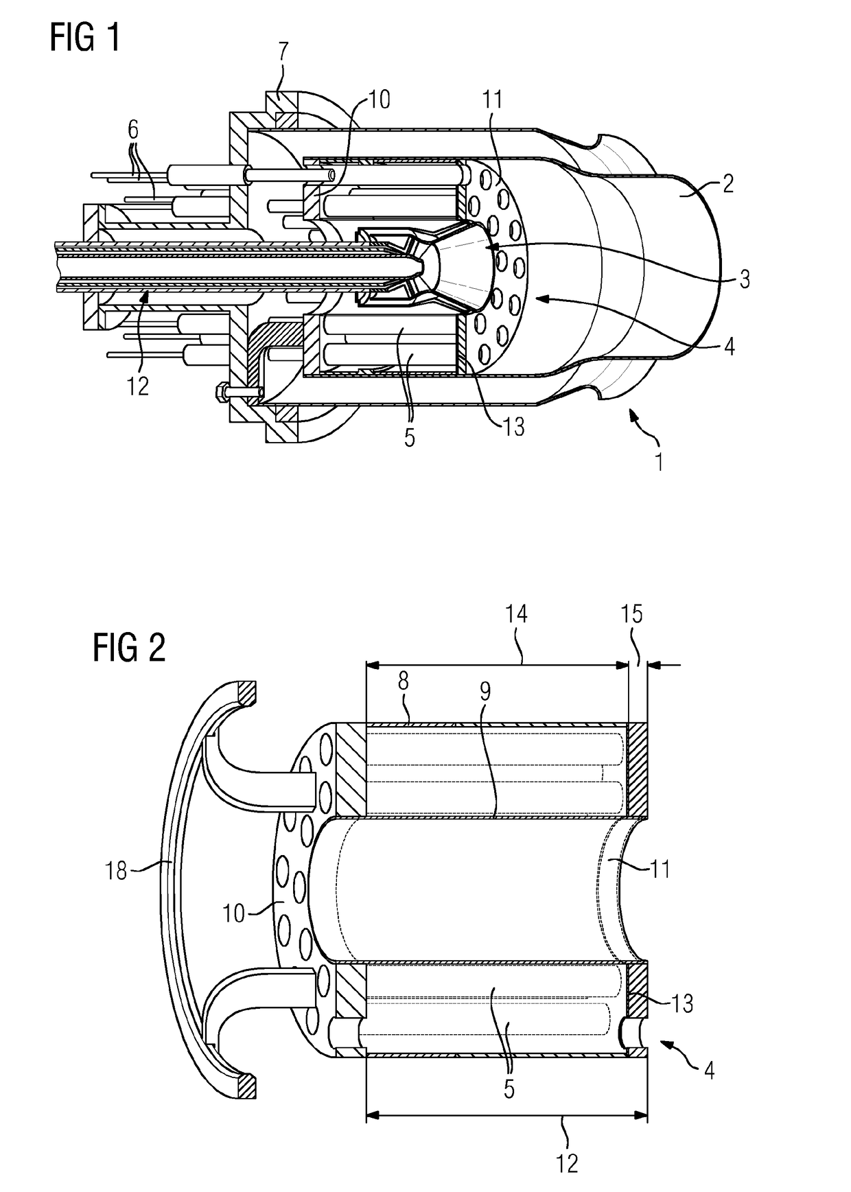
[0026]The figures show a burner arrangement 1 according to one embodiment of the present invention or components thereof. The burner arrangement 1 comprises a combustion chamber 2, a centrally arranged pilot burner 3, a mixing pipe arrangement 4 with a plurality of mixing pipes 5, which lead into the combustion chamber 2, a plurality of fuel injectors 6, which project into the mixing pipes 5 up to an appropriate position, and a mounting plate 7, which accommodates the mixing pipe arrangement 4 and serves to fasten the burner arrangement 1 to a machine housing not described in any greater detail.

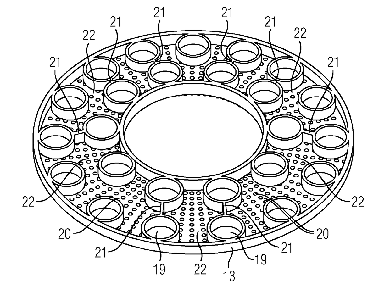
[0027]The mixing pipe arrangement 4 comprises a tubular outer wall 8, a tubular inner wall 9 arranged radially at a distance from the outer wall 8, an annular end plate 10 arranged upstream and an end plate 11 arranged downstream, which latter define an annular space 12 through which the mixing pipes 5 extend in an axial direction. The mixing pipe arrangement 4 further comprises an annular se...


PUM


Abstract

A burner arrangement having a combustion chamber, a multiplicity of mixing ducts discharging into the combustion chamber, in which ducts combustion air and fuel introduced during proper operation are mixed, and at least one resonator which has a defined resonator volume and resonator openings. The mixing ducts have mixing tubes which extend axially through an annular space defined between a tubular outer wall, a tubular inner wall arranged with the radial separation from the outer wall, an annular end plate arranged upstream and an annular end plate arranged downstream, wherein the end plates are provided with through openings which receive and / or prolong the mixing tubes. The resonator openings of the at least one resonator are designed as air ducts that extend through the downstream end plate, and the resonator volume of the at least one resonator is formed by at least one part of the annular space.

Description

CROSS REFERENCE TO RELATED APPLICATIONS[0001]This application is the US National Stage of International Application No. PCT / EP2015 / 058407 filed Apr. 17, 2015, and claims the benefit thereof. The International Application claims the benefit of German Application No. DE 102014209446.1 filed May 19, 2014. All of the applications are incorporated by reference herein in their entirety.FIELD OF INVENTION[0002]The invention relates to a burner arrangement with a combustion chamber, a plurality of mixing ducts leading into the combustion chamber, in which ducts combustion air and fuel introduced during proper operation are mixed, and at least one resonator, which comprises a defined resonator volume and resonator openings.BACKGROUND OF INVENTION[0003]Various configurations of burner arrangements are known from the prior art. During operation of a burner arrangement, such as for example the burner arrangement of a gas turbine, thermoacoustically induced combustion oscillations arise in the c...

Claims


Application Information

Patent Timeline
Patent Type & Authority Applications(United States)
IPC IPC(8): F23M20/00
CPCF23M20/005F23R3/286F23R2900/00013F23R3/42F23R3/10F23R2900/00014
Inventor BECK, CHRISTIANDEISS, OLGAFLOHR, PATRICK RONALDKNODLER, ANNA
Owner SIEMENS ENERGY GLOBAL GMBH & CO KG
Why Eureka
Try Eureka