Grip aiming device for weapons

a technology of weapons and aiming devices, which is applied in the direction of sighting devices, butts, weapons, etc., can solve the problems that devices are not particularly suitable for ease of use with rifles

Inactive Publication Date: 2017-03-23
CRIMSON TRACE
View PDF72 Cites 22 Cited by
  • Summary
  • Abstract
  • Description
  • Claims
  • Application Information

AI Technical Summary

Benefits of technology

[0004]The invention is a sighting device (sometimes referred to herein as a “device”), and a gun including the sighting device. The sighting device includes a light source and a switch to activate or deactivate the light source without a user having to move a hand (1) from a position in which the gun is being supported, or (2) from the trigger. The sighting device preferably includes a laser as the light source, a power source connectable to the laser, and a mount for mounting the device to a gun. In one embodiment, the sighting device is attached to a picatinny rail on the side of the side of the gun, and includes a compressible touch pad on which the user's fingers naturally rest when supporting the gun. The touch pad preferably includes one or more internal contacts that can each complete a separate circuit for activating the light source. The user can complete the one or more circuits by compressing (or squeezing) the compressible touch pad with sufficient force so at least one of the contacts touches a circuit trace to complete a circuit, which causes power to flow to the light source, while the user is still supporting the gun.

Problems solved by technology

Such devices are not particularly suitable for ease of use with a rifle, particularly a semi-automatic rifle with an assault design (e.g., an AR-15).

Method used


Image

  • Grip aiming device for weapons
  • Grip aiming device for weapons
  • Grip aiming device for weapons

Examples


Embodiment Construction

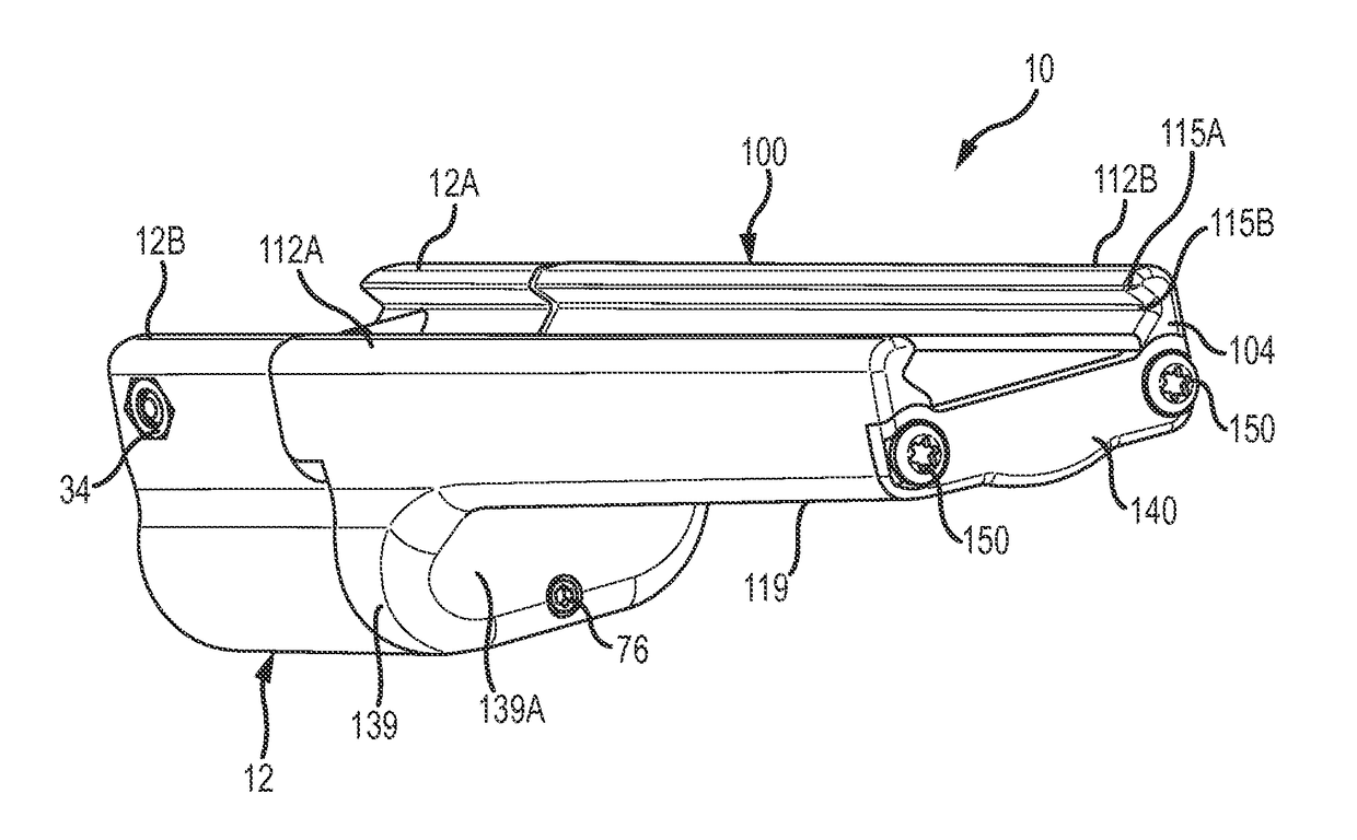
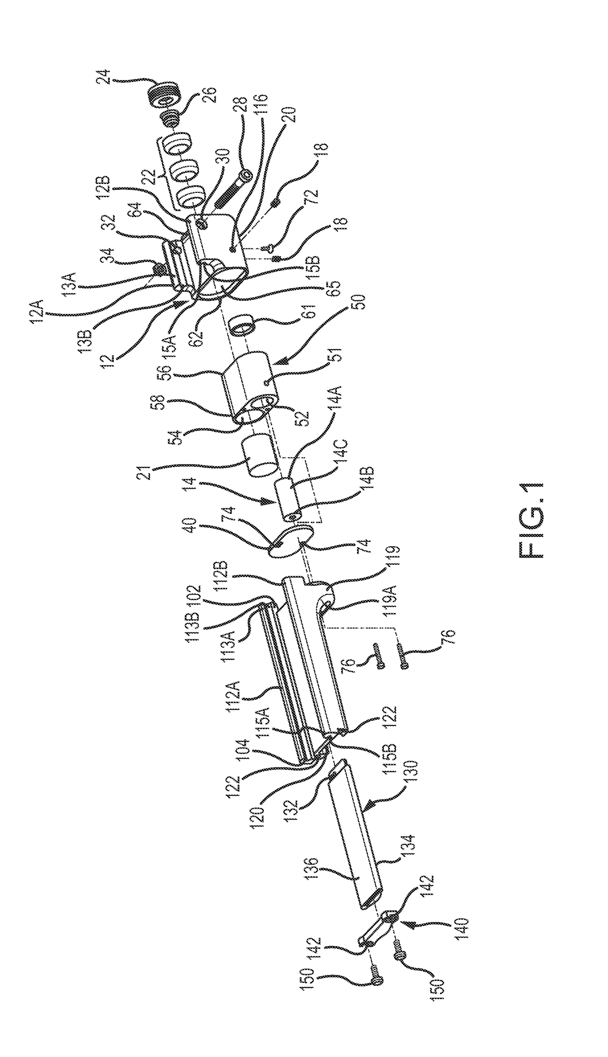
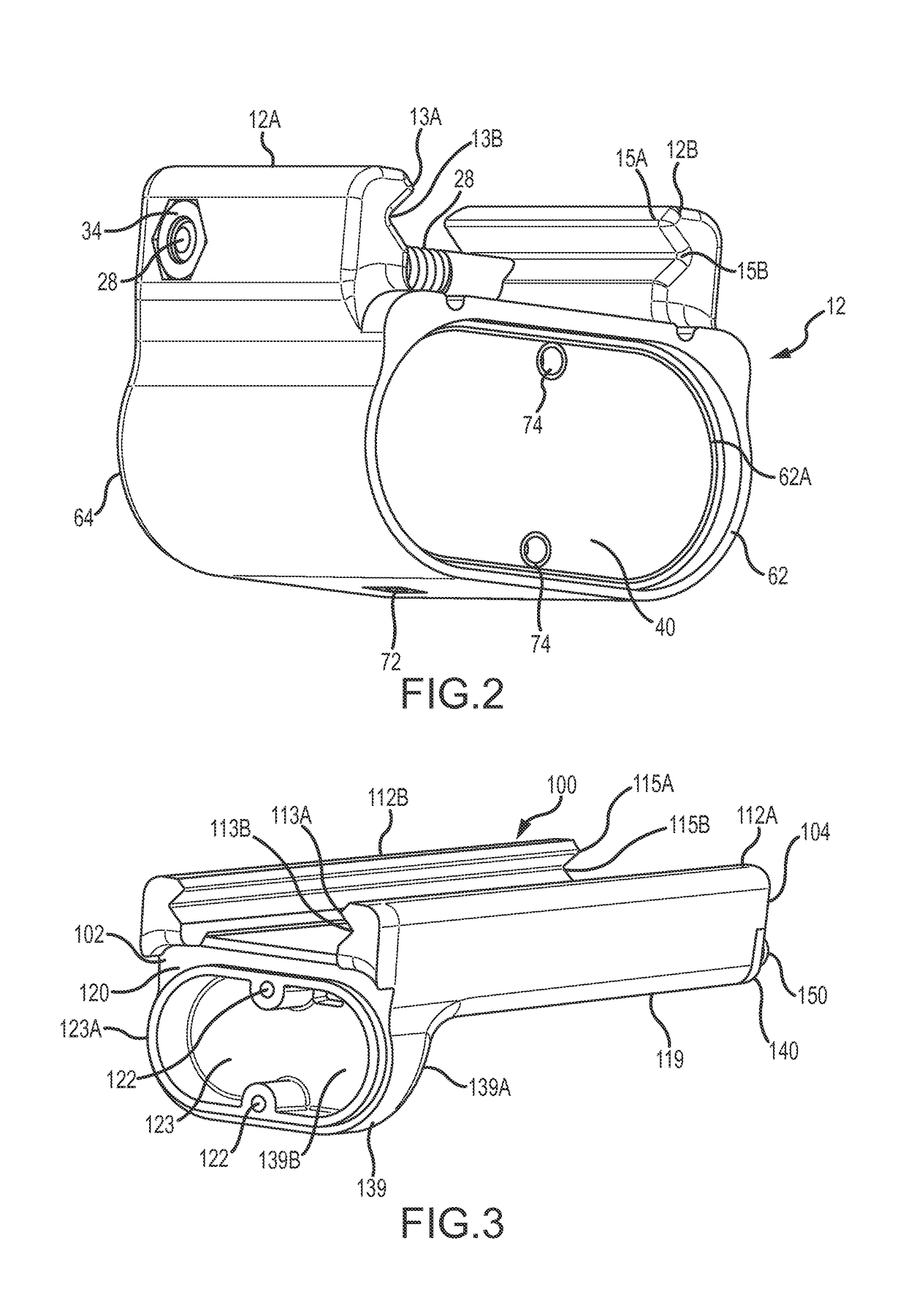
[0018]Turning now to the drawings where the purpose is to describe a preferred embodiment of the invention and not to limit same, FIGS. 1-8 show a preferred embodiment of a sighting device 10 according to the invention. Device 10 can be any structure that includes a light source and one or more power sources connectable to the light source, and a grip portion with a compressible touch pad with one or more contacts wherein the fingers of the hand with which the user supports the gun are adjacent to or touching the touch pad while that hand is in the natural position of supporting the gun. Alternatively, one or more switches may on the device and adjacent the user's fingers on the hand supporting the gun.

[0019]Preferably, device 10 is configured to be mounted on a gun 11, and most preferably on a picatinny rail 9 of the gun 11 (shown in FIGS. 9-11). Picatinny rail 9 is known in the art and is used to connect accessories to guns. As shown, picatinny rail 9 is on a side of the gun 11. A...


PUM


Abstract

A gun sighting device includes a grip and is mounted to the side of the gun. The grip has a compressible touch pad that is positioned such that a user's fingers are adjacent to, or on, the compressible touch pad when the user's hand is in the natural position of supporting the gun. The compressible touch pad can be compressed by the user's fingers to activate a light source while the user is holding the gun in the firing position, and without the user having to move his/her hand from supporting the gun or from the gun trigger.

Description

FIELD OF THE INVENTION[0001]The present invention relates to a light-emitting sighting device that can be mounted on a gun and has a switch that can be compressed to activate or deactivate the sighting device while the user is supporting and aiming the gun. The disclosures of U.S. Pat. No. 8,127,485 to Moore et al., U.S. application Ser. No. 12 / 160,213 to Moore et al., and U.S. Patent Publication No. 2014 / 030523A to Moore, which are not inconsistent with the disclosure herein, are incorporated by reference.BACKGROUND OF THE INVENTION[0002]It is known to utilize a light beam, such as a laser beam, as a sighting aid for guns. If mounted properly on a gun, the laser projects a beam of laser light in a direction generally parallel to the gun's bore. When the light beam and bore are properly aligned, the bullet (or other projectile) will strike, or strike very close to, the location of the light beam projected on a target.[0003]Such devices are not particularly suitable for ease of use w...

Claims


Application Information

Patent Timeline
Patent Type & Authority Applications(United States)
IPC IPC(8): F41G1/35F41G1/36
CPCF41G1/36F41G1/35F41C23/16
Inventor MOORE, LARRY E.MOORE, AARON
Owner CRIMSON TRACE
Why Eureka
Try Eureka