Method and apparatus for voltage control in electric power systems

a voltage control and electric power system technology, applied in the direction of electric controllers, controllers with particular characteristics, contiguous ac circuit arrangements, etc., can solve the problem of counteracting algorithmically potentially destabilizing interactions between high and low level control modules, and minimize interaction between high voltage buses. the effect of counteracting potentially destabilizing interactions

Active Publication Date: 2017-03-23
STATISTICS & CONTROL
View PDF0 Cites 12 Cited by
  • Summary
  • Abstract
  • Description
  • Claims
  • Application Information

AI Technical Summary

Benefits of technology

[0019]A method of coordinated voltage control for electric power systems is disclosed that focuses on control of distribution of reactive power between substations while minimizing the interaction between voltage control modules. The method is applicable to power systems with at least two substations and at least one load. The said control is accomplished by utilizing available control elements including transformers equipped with On Load Tap Changers and turbo generators equipped with Automatic Voltage Regulators. The said control is accomplished via the following steps. First, the algorithm assesses operating mode of each Voltage Control Module across both High Level and Low Level voltage substations. Second, the Master Voltage Controller uses a Proportional-Integral-Derivative control algorithm to regulate voltage across all turbo generators within the High Level voltages buses, where the primary process variable is the average of all high level bus voltages and secondary process variable is output by the reactive power exchange PID algorithms and the overall control action is the sum of primary and secondary control outputs. Third, the algorithm counteracts potentially destabilizing interactions between High and Low Level control modules by adjusting the Low Level set point using a correction coefficient (so called E ratio). Fourth, the system controls all the low level substations by incorporating the said correction coefficient using a set of PID control loops. Fifth, the system maintains predetermined relationships across all generators connected to each low level substation by matching functions of reactive power load rate using a flow rate balancing parameter, which is a scaling factor. Sixth, the system allows for the controller to make “course” adjustments using OLTC control mechanism to limit the exchange of reactive power with the power grid within operator specified dead band. And finally, seventh, the Voltage Control module calculates its response from the deviation of its voltage variable to manipulate the set points of the on load tap changers (OLTC) of the transformers which connect High Level Substation and Low Level Substation (or load) in a way that minimizes interaction between high voltage buses.

Problems solved by technology

Third, the algorithm counteracts potentially destabilizing interactions between High and Low Level control modules by adjusting the Low Level set point using a correction coefficient (so called E ratio).

Method used


Image

  • Method and apparatus for voltage control in electric power systems
  • Method and apparatus for voltage control in electric power systems
  • Method and apparatus for voltage control in electric power systems

Examples


Embodiment Construction

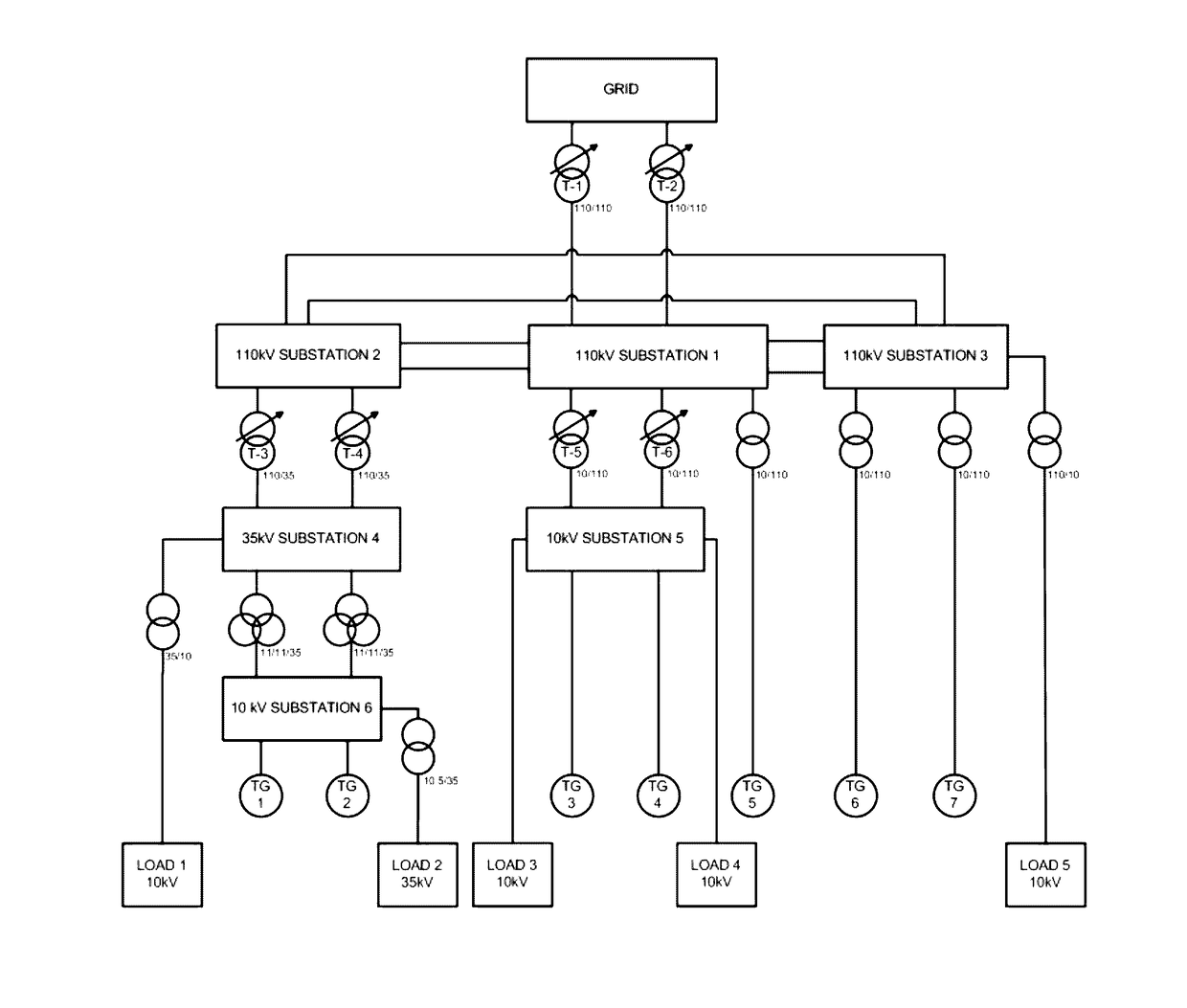
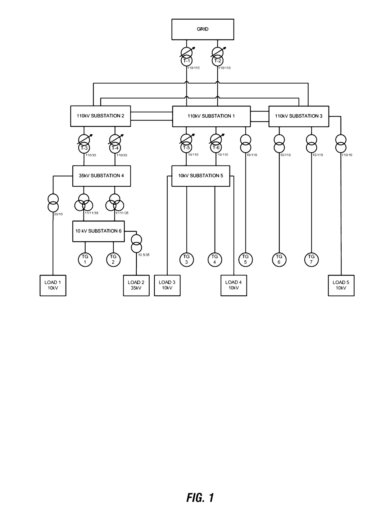
[0029]Details of the disclosed invention are illustrated on a specific example of a simplified power distribution system shown in FIG. 1, however, results and value of the invention is generalizable to any power distribution system with at least two substations and at least one load. The system shown in FIG. 1 has five sources of electrical power:[0030]1. Two transformers (T-1 and T-2) connecting the 110 kV switchyard to the grid.[0031]2. Two turbo generators (TG1 and TG2) in substation 6 connected at 11 kV.[0032]3. Two turbo generators (TG3 and TG4) in substation 5 connected at 10 kV.[0033]4. One turbo generator (TG5) in substation 1 connected at 110 kV.[0034]5. Two turbo generators (TG6 and TG7) in substation 3 connected at 110 kV.

[0035]The main system transformers (T-1 through T-6) are used in voltage control operations and are equipped with On Load Tap Changers (OLTC). Each transformer's index indicates the to / from voltage transformation. For example, transformer T-3 index is 11...


PUM


Abstract

A method and apparatus of coordinated voltage control for electric power systems with at least two substations and at least one load, a method of controlling distribution of reactive power between substations within a power system of similar parameters, and a method of reduction of interaction between voltage control modules in the said power system are disclosed. The purpose of coordinated control is to maintain acceptable voltage with minimal deviation from the set point across all elements of the power system. Disclosed coordinated control is accomplished via each substation's transformers equipped with on load tap changers (OLTC) and electrical generators Automatic Voltage Regulators (AVR) using proportional-integral-derivative control embedded in coordinated master controllers. The purpose of controlling the distribution of reactive power is to minimize power losses, maintain each busbar voltage in accordance to selected set point, maintain active and reactive power reserves, and minimizing the reactive power drawn from the transmission system by manipulating transformer's OLTC, generator's AVR, and energizing capacitors and inductors. Control of reactive power flow through the network is accomplished by the following steps:Sensing and measuring active and reactive power flow rates, and all controlled busbars voltages.Computing each voltage / reactive power controller set point and controlled variable.Using PID algorithm to compute each controller output to maintain network voltages and reactive power flows in accordance to defined set points.Implementing control actions based on computed output values.Finally, reducing the interaction between various voltage control mechanisms. It is important to ensure smooth system operation. This is accomplished by counteracting potentially destabilizing interactions between high and low level substations and corresponding control modules using specialized set point correction coefficients.

Description

CROSS-REFERENCE TO RELATED APPLICATIONS[0001]This application claims priority under 35 U.S.C. §119 to provisional application Ser. No. 62 / 220,642, filed Sep. 18, 2015, herein incorporated by reference in its entirety.BACKGROUND OF THE INVENTION[0002]An electric power system also known as an electrical grid, or just grid, is a network of interconnected components that typically involve a generation element (such as a nuclear power plant, a hydro-electric plant, or a smaller plant powered by gas fueled turbo generators), a transmission system (high voltage lines), a distribution system (lower voltage lines), and a set of customers or loads (lowest voltage levels). The connection between elements of the grid is accomplished through a set of step-up transformers (e.g., increasing voltage from a generating station to the transmission line) and step-down transformers (e.g., decreasing voltage from transmission lines into the distribution system via a substation equipped with such transfor...

Claims


Application Information

Patent Timeline
Patent Type & Authority Applications(United States)
IPC IPC(8): H02J3/18H02J13/00G05B11/36H02J3/14
CPCH02J3/18H02J3/14H02J2003/001G05B11/36H02J13/0006H02J3/16Y02E40/30H02J3/0012
Inventor SHAPIRO, VADIMNYEMCHYN, ANDRIYKOMM, ALEX
Owner STATISTICS & CONTROL
Why Eureka
Try Eureka