

Methods and apparatus for downstream dissociation of gases
- Summary
- Abstract
- Description
- Claims
- Application Information
AI Technical Summary
Benefits of technology
Problems solved by technology
Method used
Image

Examples
Embodiment Construction
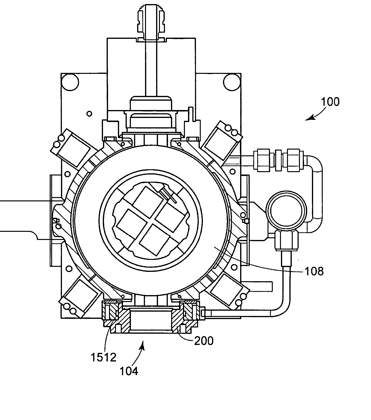
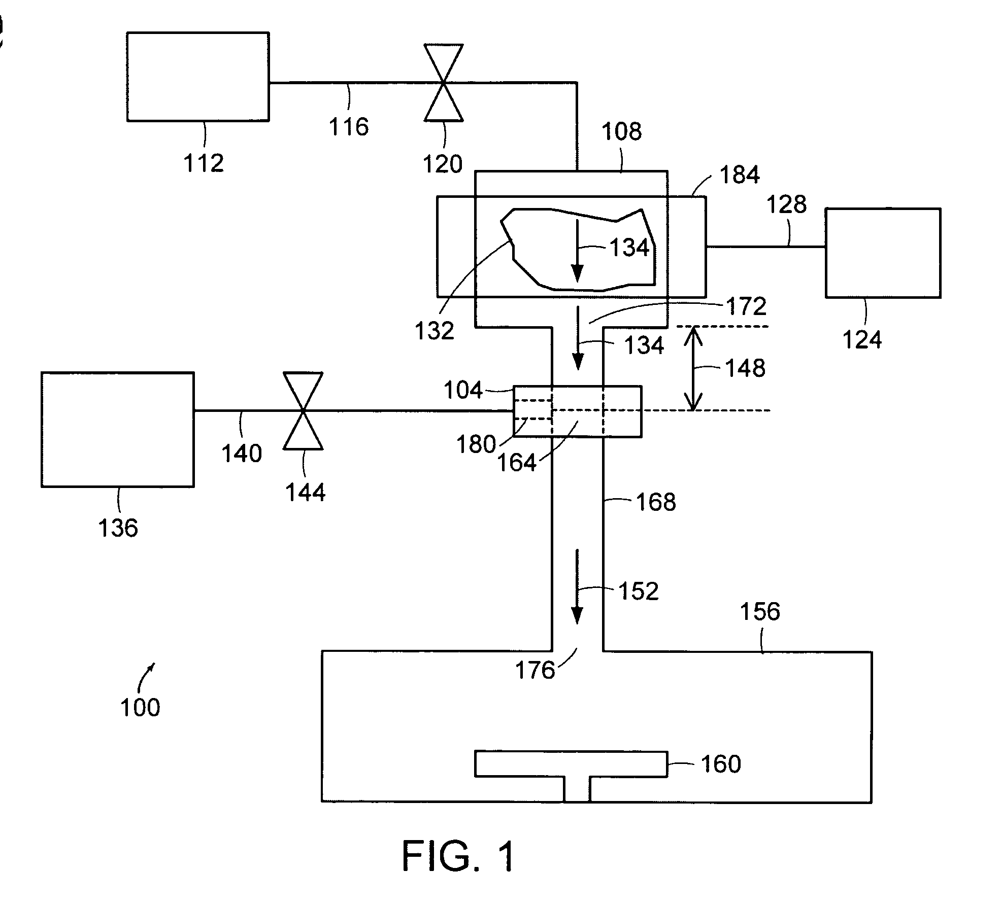
[0065]FIG. 1 is partial schematic representation of a gas dissociation system 100 for producing dissociated gases that embodies the invention. Plasmas are often used to activate gases placing them in an excited state such that the gases have an enhanced reactivity. Excitation of a gas involves elevating the energy state of the gas. In some cases, the gases are excited to produce dissociated gases containing ions, free radicals, atoms and molecules. The system 100 includes a plasma gas source 112 connected via a gas line 116 to a plasma chamber 108. A valve 120 controls the flow of plasma gas (e.g., O2, N2, Ar, NF3, H2 and He) from the plasma gas source 112 through the gas line 116 and into the plasma chamber 108. The valve 120 may be, for example, a solenoid valve, a proportional solenoid valve, or a mass flow controller. A plasma generator 184 generates a region of plasma 132 within the plasma chamber 108. The plasma 132 comprises plasma activated gas 134, a portion of which flows ...
PUM
| Property | Measurement | Unit |
|---|---|---|
| Length | aaaaa | aaaaa |
| Length | aaaaa | aaaaa |
| Length | aaaaa | aaaaa |
Abstract
Description
Claims
Application Information