Process for Polycrystalline film silicon growth

Inactive Publication Date: 2001-08-28
ALLIANCE FOR SUSTAINABLE ENERGY
View PDF6 Cites 392 Cited by
  • Summary
  • Abstract
  • Description
  • Claims
  • Application Information

AI Technical Summary

Benefits of technology

The present invention is directed at a process employing chemical vapor transport to grow polycrystalline films on substrates. The present invention is also directed toward a...

Problems solved by technology

While the temperature required for the onset of growth is comparatively low, the iodides tend to yield bulk crystal featu...

Method used


Image

  • Process for Polycrystalline film silicon growth
  • Process for Polycrystalline film silicon growth
  • Process for Polycrystalline film silicon growth

Examples


Embodiment Construction

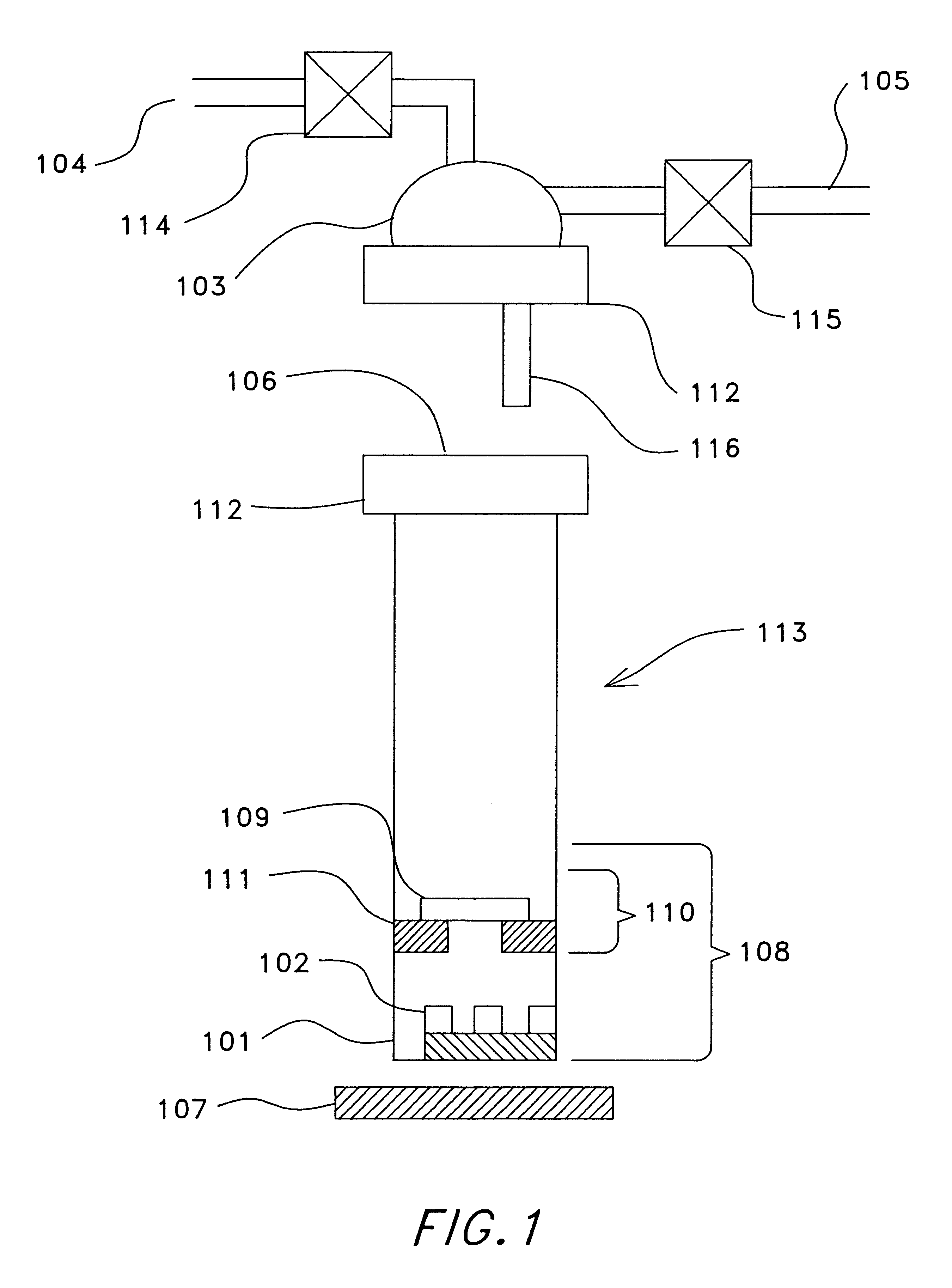
With reference to FIG. 1, in the preferred embodiment of the invention reactor 113 is a quartz tube 2" in diameter and 15" long, and having one end sealed and the other end fitted with a glass joint. Reactor 113 is placed vertically, with its sealed end residing in a heating mantle and disposed below its open end. Reactor 113 is charged with at least 0.012 grams of iodine crystals per cubic centimeter of confinement zone 108 volume and preferably with between 0.030 and 0.060 grams of iodine crystals per cubic centimeter of confinement zone 108 volume. Thus, in a typical experiment, approximately 10 g of solid iodine, which serves as the source of transport vapor 102, is placed into the bottom of reactor 113. A solid silicon plate having a weight of 5% or greater the weight of iodine added is also placed in the bottom of reactor 113. The amount of silicon added is adjusted such that the mole ratio of silicon to iodine exceeds 1:4. The silicon plate serves as coating source reagent 10...


PUM

PropertyMeasurementUnit
Temperatureaaaaaaaaaa
Thicknessaaaaaaaaaa
Pressureaaaaaaaaaa

Abstract

A process for depositing polycrystalline silicon on substrates, including foreign substrates, occurs in a chamber at about atmospheric pressure, wherein a temperature gradient is formed, and both the atmospheric pressure and the temperature gradient are maintained throughout the process. Formation of a vapor barrier within the chamber that precludes exit of the constituent chemicals, which include silicon, iodine, silicon diiodide, and silicon tetraiodide. The deposition occurs beneath the vapor barrier. One embodiment of the process also includes the use of a blanketing gas that precludes the entrance of oxygen or other impurities. The process is capable of repetition without the need to reset the deposition zone conditions.

Description

CHEMICAL VAPOR TRANSPORT--general principlesChemical Vapor Transport (generally known as CVT) is a crystal growth process in which the materials to be grown are transported to the growth zone as volatile compounds that chemically react or decompose to give the material and a by-product. The CVT technique could be used in growth of either bulk crystals or thin films on a substrate. CVT may be categorized as either an open system or a closed system depending on the usage of the gas components. In closed systems, the source material and the growth zone are both contained in a sealed reaction chamber, material transport is accomplished by gas phase diffusion and convection due to temperature difference without the aid of a carrier gas, and the by-product is recycled. The advantage of a closed system is that only a small amount of transport medium is needed, but it is unsuitable for production-scale operation because unloading the grown crystals and replenishing the source material and s...

Claims


Application Information

Patent Timeline
IPC IPC(8): C01B33/00C01B33/039C23C16/22C23C16/44C23C16/46C30B25/02C23C16/448C23C16/24C23C16/54C23C16/458H01L21/02H01L21/285C01B33/02H01L21/205H01L31/04
CPCC01B33/039C23C16/24C23C16/4402C23C16/4418C23C16/4488H01L21/28525C23C16/46C23C16/54C30B25/02C30B29/06C23C16/4583
Inventor WANG, TIHUCISZEK, THEODORE F.
Owner ALLIANCE FOR SUSTAINABLE ENERGY
Why Eureka
Try Eureka