Side mount hoist ring

a hoist ring and side mount technology, applied in the field of hoist rings, can solve the problems of inability to adapt to use with "as forged" parts, high cost of machining operations on parts, and inability to meet the requirements of prior configurations, etc., to achieve the effect of avoiding several expensive machining operations and avoiding the possibility of machining failures

Inactive Publication Date: 2001-07-31
MJT HLDG
View PDF19 Cites 49 Cited by
  • Summary
  • Abstract
  • Description
  • Claims
  • Application Information

AI Technical Summary

Problems solved by technology

It is well known that machining operations on parts are expensive in time and materials.
The prior art assemblies generally require numerous machining operations, and their designs are not readily adaptable for use with "as forged" parts.
In particular, the close tolerances generally required in prior configurations could not be made from forgings without several expensive machining operations.
However, due to the manner in which stress is distributed through the circular ring and elongated channel, for a given size, the load capacity of the assembly is significantly less than a comparably sized center pull hoist ring.
Thus, this previous swiveling and pivoting side pull hoist ring assembly utilizing a circular hoist ring is undesirably limited to medium load capacities compared to equivalently sized center pull hoist ring assemblies.
Although, for a given sized assembly, the straight segment and U-shaped channel act to somewhat enhance the load capacity compared to the use of the circular ring, the semi-circular portion of the ring can still undesirably flex, due to bending stresses imposed during lifting.
This flexing limits the load capacity of the assembly.
Another problem with the previous swiveling and pivoting side mount hoist ring assemblies is that the lift ring is only captively restrained in the assembly when the assembly is mounted to the flat surface of an object.
Undesirably, these prior art assemblies rely on the surface of the lifting object to retain the lift ring.
Thus, when uninstalled, undesirably, the ring can be misplaced or lost.
Where sparks must be avoided, for example, in explosive environments and the like, brass or plastic, for example, can be used, but with a very substantial sacrifice in strength.

Method used


Image

  • Side mount hoist ring
  • Side mount hoist ring
  • Side mount hoist ring

Examples


Embodiment Construction

Referring now to the drawings wherein like reference numerals designate identical or corresponding parts throughout the several views.

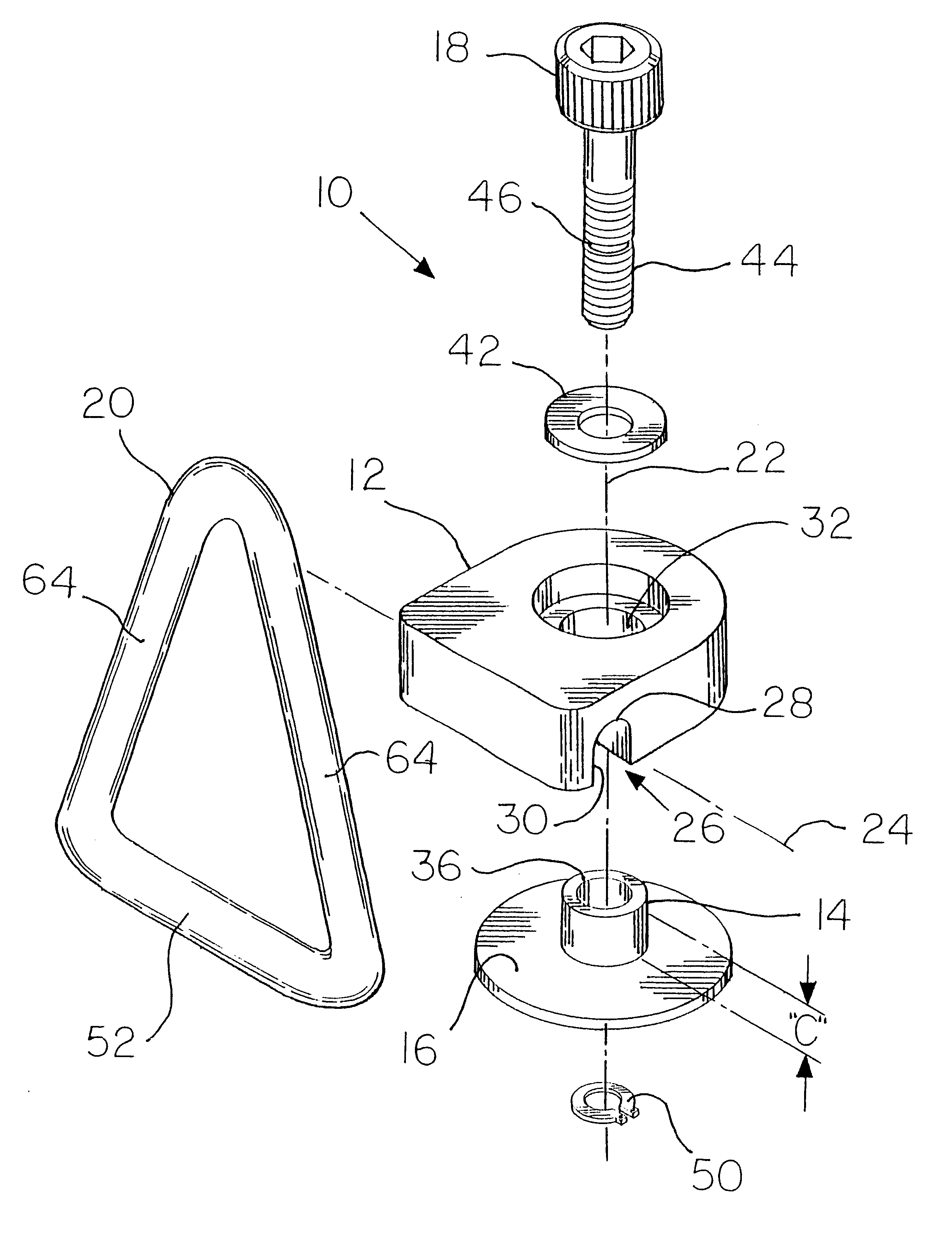
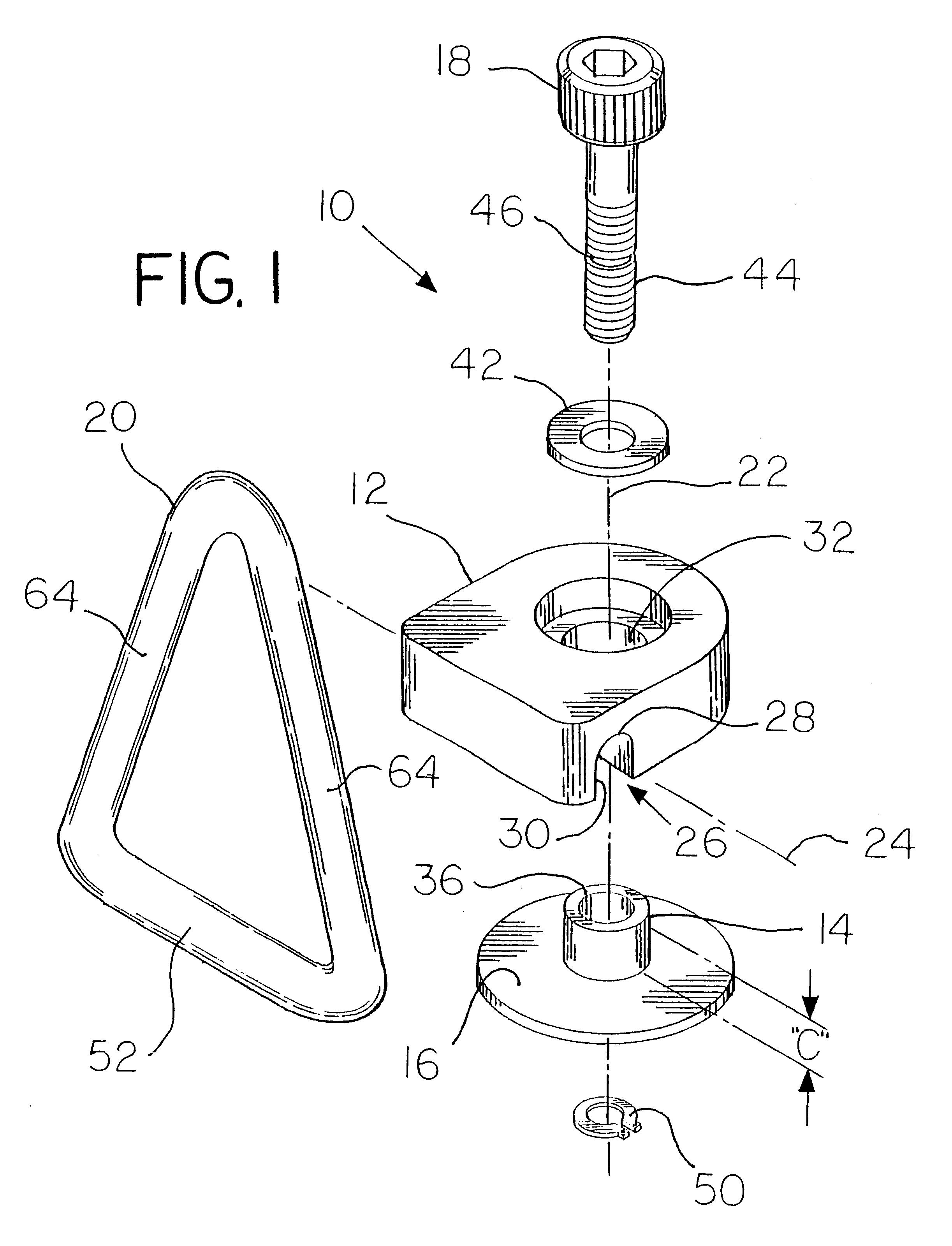
Referring particularly to the drawings, there is illustrated generally at 10 a side pull hoist ring assembly. The side pull hoist ring assembly 10 includes a body 12, a cylindrical bushing 14, a load bearing flange 16, a mounting member 18, and a lift ring 20.

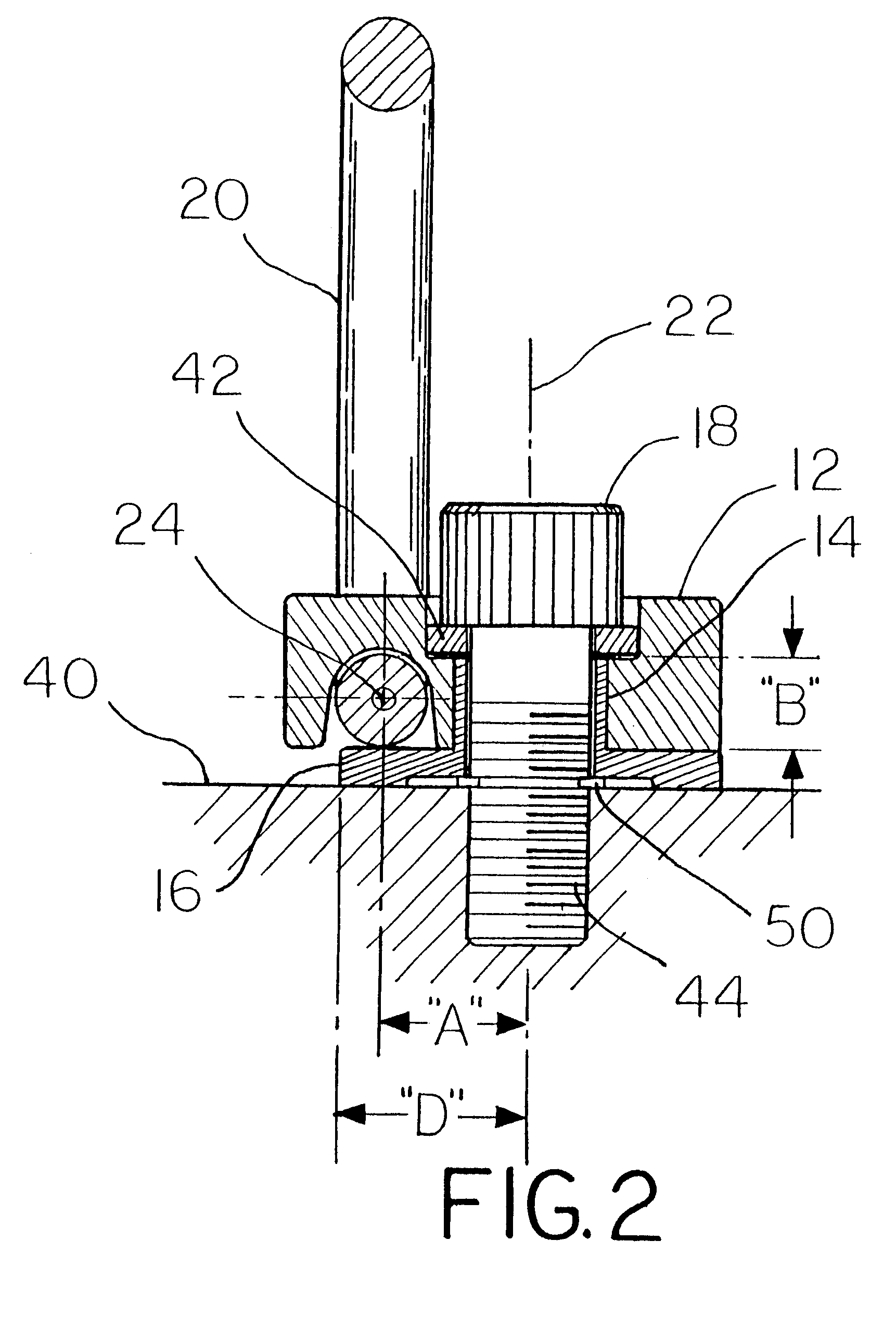
The body 12 includes a longitudinal axis 22 and a lateral axis 24 that do not intersect. The lateral axis 24 is generally normal to the longitudinal axis 22 and the two axes are offset from each other by an offset distance noted by dimension "A". The body includes a generally U-shaped linear channel 26 extending generally along the lateral axis 24. The U-shaped linear channel has a generally arcuate bottom 28 and an open mouth 30. A generally cylindrical bore 32 is provided in the body 12 extending generally concentrically with the longitudinal axis 22. The generally cylindrical bore 32 has an ax...


PUM


Abstract

A side mount hoist ring assembly adapted to swivel through a full 360 degrees and pivot through a full 180 degrees that is more economical and simple to fabricate since the pivot axis is offset a distance from the swivel axis. The lift comprises a body, a cylindrical bushing, a load bearing flange, a closed lifting loop, and a threaded mounting member. Lifting loads exerted on the lifting loop induce bending stress on the mounting member which are compensated for by the load bearing flange.

Description

1. Field of the InventionThe invention relates in general to hoist rings and, in particular, to a side mount hoist ring adapted to be mounted on an object to be lifted. The side mount hoist ring is adapted to swivel through a full 360 degrees and pivot through a full 180 degrees, is more economical to fabricate than comparable center mount hoist ring assemblies, and maintains or exceeds the load capacity of a comparable size center mount hoist ring assembly.2. Description of the Prior ArtVarious hoist ring assemblies have been proposed previously. Recently there has been a need to develop hoist ring assemblies that are attachable to objects to be lifted while being able to continuously swivel 360 degrees in one direction and tilt approximately 180 degrees in another. Hoist ring assemblies having these properties have been found very desirable by industry. For example, in Tsui et al U.S. Pat. No. 4,705,422, and Tsui et al U.S. Pat. No. 5,848,815 such swiveling and tilting hoist ring ...

Claims


Application Information

Patent Timeline
Patent Type & Authority Patents(United States)
IPC IPC(8): B66C1/62B66C1/66
CPCB66C1/66Y10T403/32213
Inventor ALBA, TONY J.
Owner MJT HLDG
Why Eureka
Try Eureka