Fuel injection valve for internal combustion engines

a technology for internal combustion engines and fuel injection valves, which is applied in the direction of fuel injection apparatus, machine/engines, feed systems, etc., can solve the problems of increased weakening in this area, high surface pressure, and increased strength problems in the vicinity

Inactive Publication Date: 2002-12-31
ROBERT BOSCH GMBH
View PDF11 Cites 18 Cited by
  • Summary
  • Abstract
  • Description
  • Claims
  • Application Information

AI Technical Summary

Problems solved by technology

As regards future fuel injection valves with even higher injection pressures than are currently customary, strength problems can therefore arise in the vicinity of the annular groove.
Due to the circular cross se

Method used


Image

  • Fuel injection valve for internal combustion engines
  • Fuel injection valve for internal combustion engines
  • Fuel injection valve for internal combustion engines

Examples


Embodiment Construction

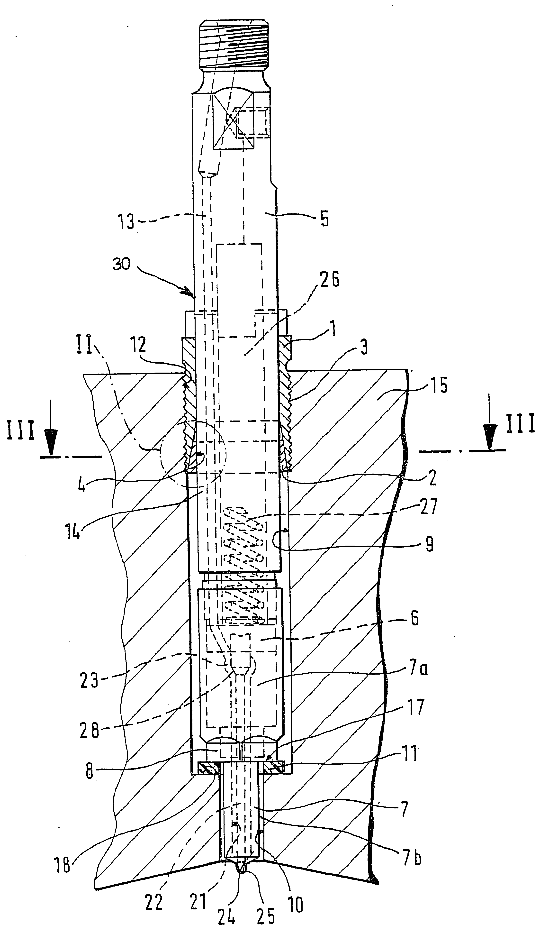
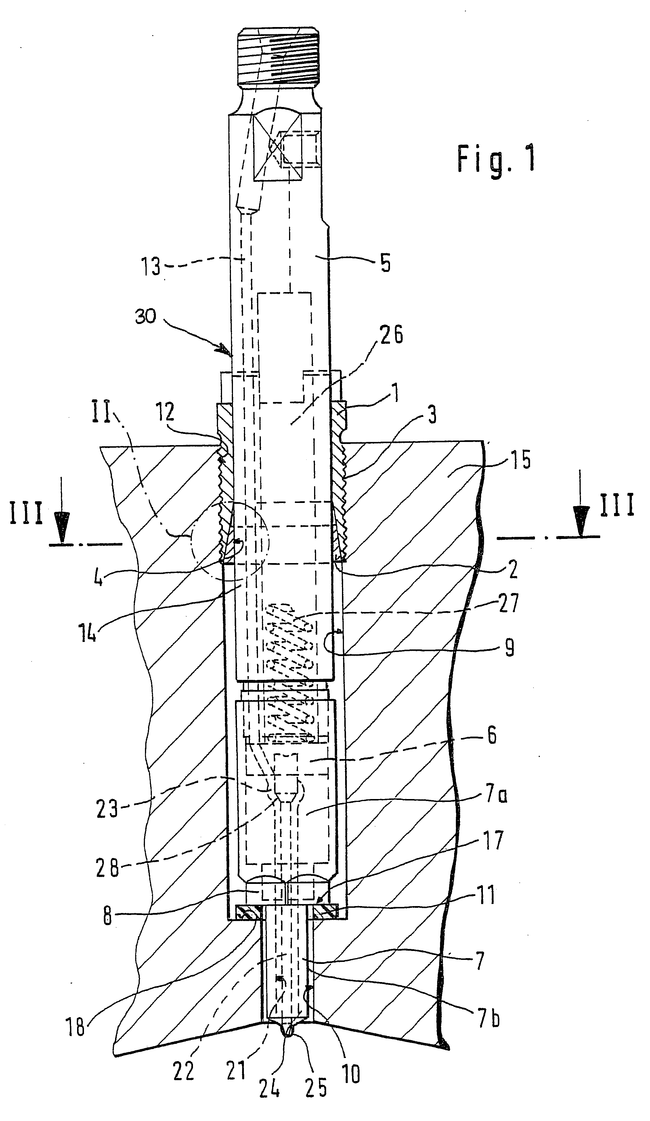
FIG. 1 shows a full view of a fuel injection valve according to the invention and its installation in the internal combustion engine. The following description is limited to the parts of the fuel injection valve that are essential to the invention.

The valve body 30 is comprised of a cylindrical valve holding body 5 and a valve base body 7, wherein the valve base body 7 is clamped against the valve holding body 5 by means of a clamping sleeve 8, with the interposition of an intermediary washer 6. The valve base body 7 is divided into two cylindrical sections, wherein the section 7a oriented toward the valve holding body 7 is embodied with a larger diameter than the section 7b remote from the valve holding body 5. The valve base body 7 has a bore 21 embodied in it which contains a piston-shaped, axially movable valve member 22. The closing force of at least one spring 27, which is disposed in a spring chamber 26 embodied in the valve holding body 5, presses the valve member 22 against...


PUM


Abstract

A fuel injection valve for internal combustion engines, having an associated valve body, wherein the valve body is inserted into the receiving bore of the housing of an internal combustion engine and-by means of a clamping element, which is screwed into an internal thread embodied at the end of the receiving bore remote from the combustion chamber, and a support element disposed in an annular groove-is clamped with an annular shoulder embodied on the valve body against a contact surface embodied in the bore. The inner circumference surface of the clamping element and the outer circumference of the support element are conically embodied so that the axial movement of the clamping element when it is screwed in, exerts a radial force on the support element as a result of which it is pressed with its cylindrical inner circumference surface into the annular groove and as a result, a high axial force can be transmitted to the valve body without high surface pressures occurring as a result.

Description

PRIOR ARTThe invention is based on a fuel injection valve for internal combustion engines according to the preamble to claim 1. A fuel injection valve of this kind has been disclosed by the published, non-examined German patent disclosure DE-OS 2 303 506. The fuel injection valve has an associated valve body which can be comprised of a number of parts. The valve body tapers toward the combustion chamber so that at least one annular shoulder is embodied on its circumference surface and rests against a contact surface embodied in the receiving bore. The valve holding body has an annular groove embodied on it, in which a support element is disposed, which is embodied as a snap ring that is open in at least one location on its circumference. The snap ring is dimensioned so that it protrudes with approximately half of its thickness beyond the valve holding body. At the end of the receiving bore remote from the combustion chamber, there is a clamping element embodied as a union nut which ...

Claims


Application Information

Patent Timeline
IPC IPC(8): F02M61/00F02M61/14F02M61/16
CPCF02M61/14
Inventor FERRARO, GIOVANNIEGELER, HANSJOERGELLWANGER, KLAUS
Owner ROBERT BOSCH GMBH
Why Eureka
Try Eureka