Fuel injector

a fuel injector and injector technology, applied in the field of fuel injectors, can solve the problems of reducing the service life of actuators such as solenoid actuators or piezoelectric actuators, and achieve the effects of reducing the return quantity of the injector, high injection pressure, and high injection pressur

Inactive Publication Date: 2010-04-29
ROBERT BOSCH GMBH
View PDF7 Cites 12 Cited by
  • Summary
  • Abstract
  • Description
  • Claims
  • Application Information

AI Technical Summary

Benefits of technology

[0004]In a fuel injector having an injector housing that includes a pressure chamber from which highly pressurized fuel is injected into a combustion chamber of an internal combustion chamber when the pressure in a control chamber is relieved into a pressure relief chamber with the aid of a control valve device, this object is attained by the fact that the injector has a low-pressure supply line that is connected to a low-pressure return via a flushing path that extends through the pressure relief chamber. The flushing path can be used to cool temperature-critical regions of the injector in the pressure relief chamber. This makes it possible to implement higher injection pressures than with conventional injectors.
[0005]A preferred exemplary embodiment of the fuel injector is characterized in that the flushing path extends along or past parts of the control valve device and / or an actuator. In order to achieve extremely high injection pressures, fuel injectors can be embodied in leakage-reduced or leakage-free designs by omitting a low-pressure stage. This makes it possible to significantly reduce the return quantity of the injector. Essentially, the control quantity of the servo circuit remains, but assumes very high temperatures because the control quantity is released from the system pressure via an outlet throttle. In the context of the present invention, it has turned out that particularly in injector designs in which the control valve device and the associated actuator are situated in the injector head, the temperature in the head region exceeds the permissible range. In the head region, the heat dissipation via the injector housing is low. This reduces the service life of actuators such as solenoid actuators or piezoelectric actuators. The flushing path according to the invention makes it possible to selectively cool, at least partially, temperature-critical parts of the control valve device and / or actuator.

Problems solved by technology

This reduces the service life of actuators such as solenoid actuators or piezoelectric actuators.

Method used


Image

  • Fuel injector
  • Fuel injector

Examples


Embodiment Construction

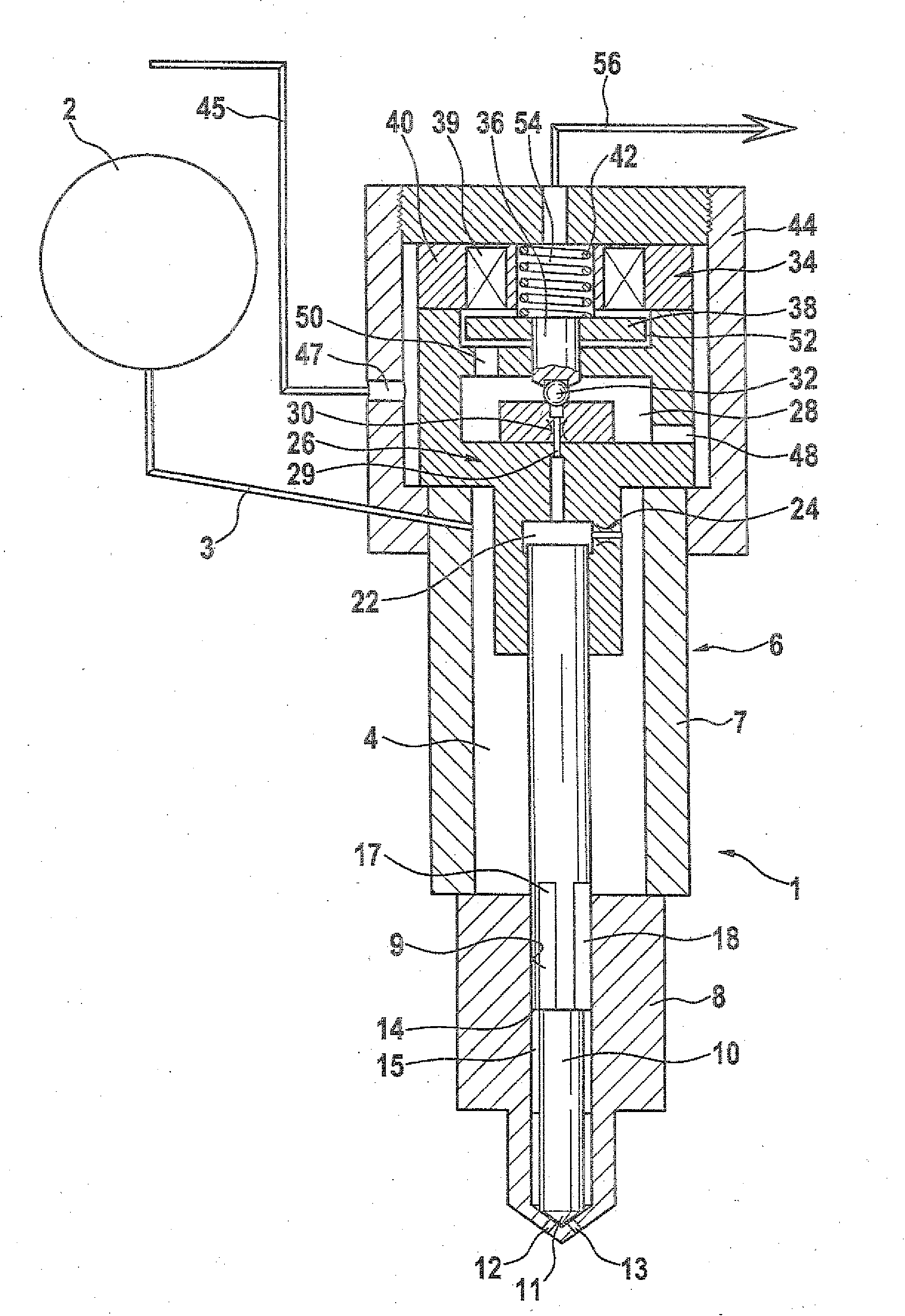
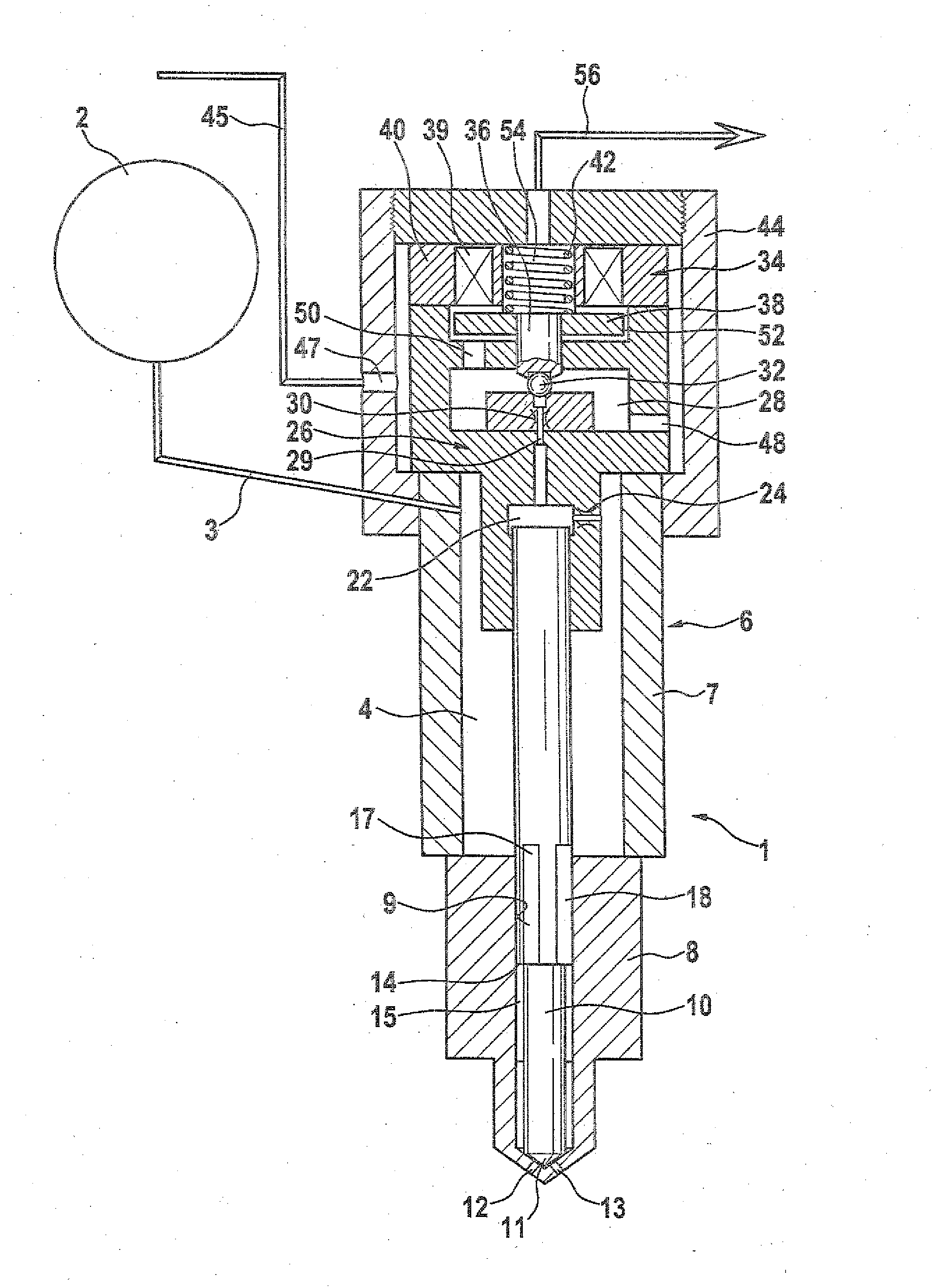
[0015]The accompanying FIGURE depicts a schematic longitudinal section through a fuel injector 1. The fuel injector 1 is supplied with highly pressurized fuel from a high-pressure reservoir or more precisely, a high-pressure fuel source 2. A supply line 3 connects the fuel injector 1 to the high-pressure reservoir 2. Inside the fuel injector 1, the supply line 3 feeds into a high-pressure connection chamber 4, which is enclosed by an injector housing 6.

[0016]The injector housing 6 encloses an injector body 7 and a nozzle body 8 equipped with a central guide bore 9. A nozzle needle 10 is guided so that it is able to move back and forth in the guide bore 9. The nozzle needle 10 has a tip 11 that opens or closes a flow connection between injection openings 12, 13 and a pressure chamber 15 when the nozzle needle 10 moves away from or toward the combustion chamber.

[0017]The nozzle needle 10 has a pressure shoulder 14 formed onto it, which is situated in the pressure chamber 15. The nozzl...


PUM


Abstract

The invention relates to a fuel injector comprising an injector housing having a pressure chamber from which fuel subjected to a high pressure is injected into a combustion chamber of an internal combustion engine when the pressure in a control chamber expands into a pressure relief chamber by a control valve device. The aim of the invention is to create a fuel injector which has a long service life even though subjected to high pressures. To this end, the injector includes a low-pressure supply line which is connected to a low-pressure return line by a purge path extending through the pressure relief chamber.

Description

[0001]An injector housing that includes a pressure chamber from which highly pressurized fuel is injected into a combustion chamber of an internal combustion chamber when the pressure in a control chamber is relieved into a pressure relief chamber with the aid of a control valve device.PRIOR ART[0002]In order to introduce fuel into direct-injection diesel engines, stroke-controlled fuel injection systems are used in which the injection pressure can be adapted to the load and engine speed.DISCLOSURE OF THE INVENTION[0003]The object of the invention is to create a fuel injector with the defining characteristics of the preamble to claim 1, which has a long service life even at high injection pressures.[0004]In a fuel injector having an injector housing that includes a pressure chamber from which highly pressurized fuel is injected into a combustion chamber of an internal combustion chamber when the pressure in a control chamber is relieved into a pressure relief chamber with the aid of...

Claims


Application Information

Patent Timeline
Patent Type & Authority Applications(United States)
IPC IPC(8): F02M47/02
CPCF02M47/027F02M53/04F02M2700/077F02M63/007F02M2547/003F02M55/002
Inventor MAGEL, HANS-CHRISTOPH
Owner ROBERT BOSCH GMBH
Why Eureka
Try Eureka