Superconducting magnet system with refrigerator

Inactive Publication Date: 2006-03-30
BRUKER BIOSPIN
View PDF12 Cites 30 Cited by
  • Summary
  • Abstract
  • Description
  • Claims
  • Application Information

AI Technical Summary

Benefits of technology

[0021] In a particularly preferred embodiment of the invention, the section of the refrigerator which contains the regenerator is disposed at a location in the cryostat which has a minimum magnetic field during operation, e.g. in the radial space between a main and shielding coil of the magnet arrangement or radially outside of the magnet coil approximately in the region of its center plane. Interaction between the regenerator material and the main magnetic field is thereby minimized.
[0022] The cryostat and refrigerator are preferably designed and dimensioned such that no additional helium must be refilled in the cryostat during operation. This increases the user friendliness of the cryostat and permits continuous operation of the magnet arrangement over very long time periods.
[0023] In a preferred embodiment, the second helium tank is disposed above the first helium tank. The second helium tank can thereby serve the hydrostatic function of keeping the first helium tank at atmospheric pressure.
[0024] In a particularly preferred embodiment of the invention, the closed helium loop comprises a return line to return the supplied helium, the return line having a pressure

Problems solved by technology

This reduces the overal

Method used


Image

  • Superconducting magnet system with refrigerator
  • Superconducting magnet system with refrigerator
  • Superconducting magnet system with refrigerator

Examples


Embodiment Construction

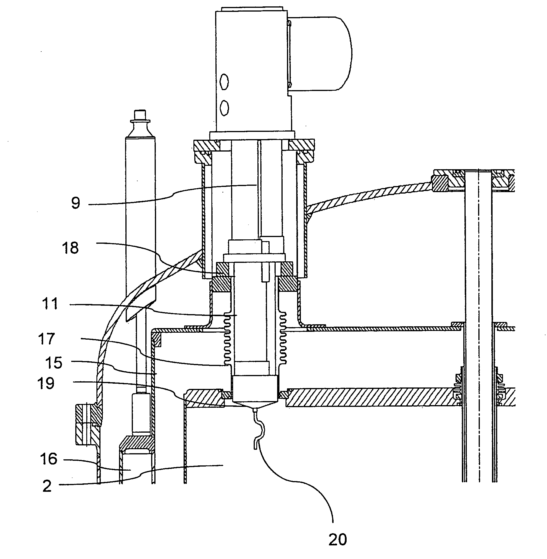
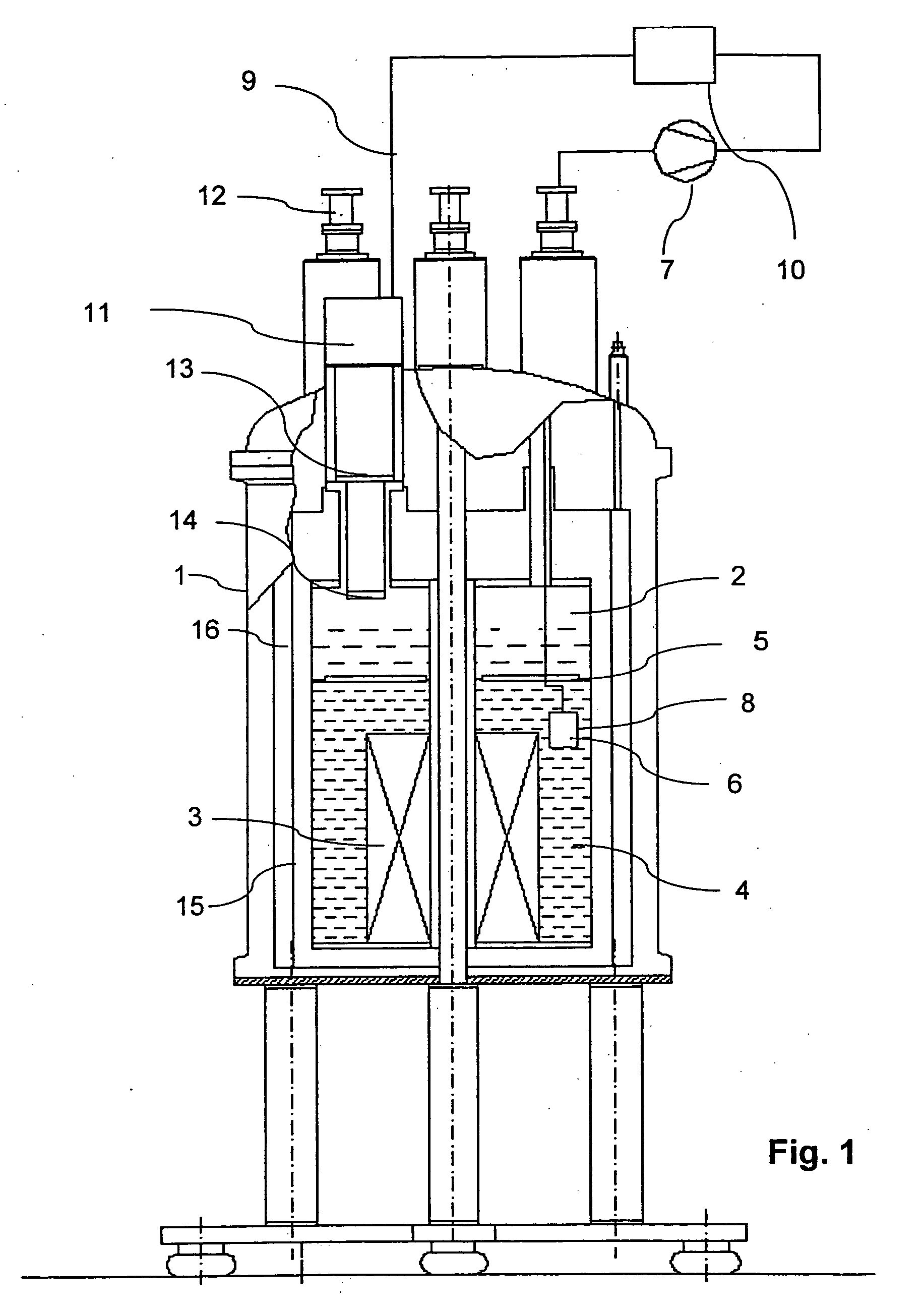
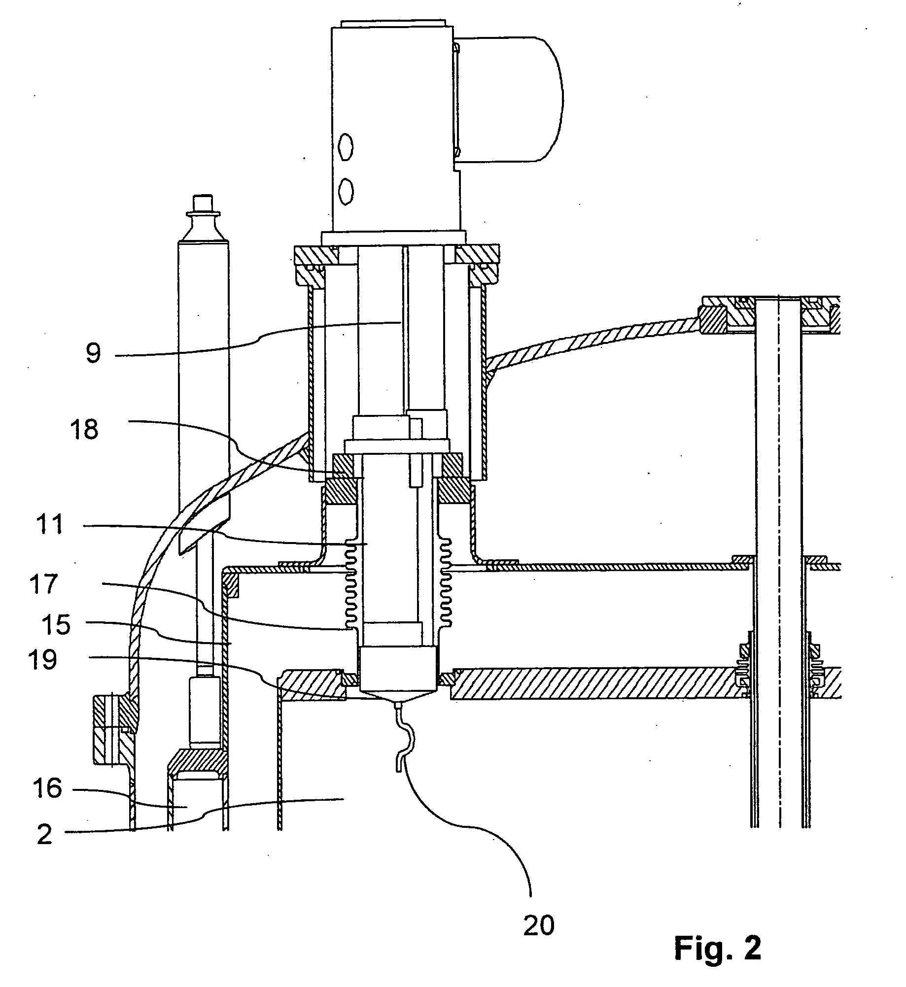
[0035]FIG. 1 shows an inventive cryostat 1 with a first helium tank 4 which is disposed in the cryostat 1 and which contains a magnet coil 3 for generating a highly homogeneous magnetic field. A second helium tank 2 is disposed above the first helium tank 4 and is separated from the first helium tank 4 by a thermal barrier 5. The second helium tank 2 contains liquid helium at atmospheric pressure p0 or at a pressure level p1 which is slightly higher than atmospheric pressure p0 and at a temperature of more than 3 K, preferably 4.2 K. The two helium tanks 2, 4 communicate with each other such that helium can flow from the upper, second helium tank 2 into the lower, first helium tank 4 where the helium is further cooled (undercooled) to a temperature of considerably less than 3 K, preferably 1.8 K, using a cooling means. Towards this end, the helium is pumped via the cooling means 6 through a pump 7 and is expanded using a Joule-Thomson valve. A heat exchanger which may be designed in...


PUM


Abstract

A cryostat (1) with a first helium tank (4) which contains helium at an operating temperature T1<3 K, and a second helium tank (2) which is connected to the first helium tank (4) and contains liquid helium at an operating temperature T2>3 K, wherein a cooling means (6) is provided in the first helium tank (4) which generates an operating temperature T1<3 K in the first helium tank (4), wherein the cooling means (6) is designed as a Joule-Thomson valve with downstream heat exchanger from which pumped helium is transported to a room temperature region outside of the cryostat (1) is characterized in that a refrigerator (11) is provided whose cold end (19) projects into the second helium tank (2) and the supplied helium is returned during normal operation in a closed loop along the refrigerator (11) and into the second helium tank (2), thereby being pre-cooled and liquefied at the cold end (19) of the refrigerator (11). The inventive cryostat minimizes helium consumption, thereby permitting continuous measuring operation.

Description

[0001] This application claims Paris Convention priority of DE 10 2004 012 416.7 filed Mar. 13, 2004 and of EP 040 241 33.3 filed Oct. 9, 2004 the entire disclosure of which are both hereby incorporated by reference. BACKGROUND OF THE INVENTION [0002] The invention concerns a cryostat with a first helium tank which contains helium at an operating temperature T1<3 K, and a second helium tank which is connected to the first helium tank, and contains liquid helium at an operating temperature T2>3 K, wherein the first helium tank has a cooling means which generates an operating temperature T1<3 K in the first helium tank, wherein the cooling means is designed as a Joule-Thomson valve with downstream heat exchanger and supplies pumped helium to a room temperature region outside of the cryostat. A magnet system of this type is disclosed in U.S. Pat. No. 5,220,800. [0003] Superconducting magnet systems of this type generally comprise a cryostat with two chambers, with a supercondu...

Claims


Application Information

Patent Timeline
IPC IPC(8): F25B19/00F25B9/00
CPCF25B9/02F25B9/10H01F6/04F25B2400/17F25D19/006F25B9/145
Inventor ROTH, GERHARD
Owner BRUKER BIOSPIN
Why Eureka
Try Eureka