Conductive Coating of Implants with Inductive Link

Inactive Publication Date: 2009-12-03
MED EL ELEKTROMEDIZINISCHE GERAETE GMBH
View PDF13 Cites 27 Cited by
  • Summary
  • Abstract
  • Description
  • Claims
  • Application Information

AI Technical Summary

Benefits of technology

[0011]Embodiments of the present invention are direct to an implantable device that includes an implanted coil for receiving a transcutaneous coil signal from an external transmitting coil. A coil housing

Problems solved by technology

This requires that the implanted receiving coils are not electrically shielded, which would interfere with the signal transfer.
Just as with any surgical procedure, there is also some risk during implant surgery of postoperative infections at the surgical site.
Depending on several factors (such as the silver concentration) a problem may arise i

Method used


Image

  • Conductive Coating of Implants with Inductive Link
  • Conductive Coating of Implants with Inductive Link
  • Conductive Coating of Implants with Inductive Link

Examples


Embodiment Construction

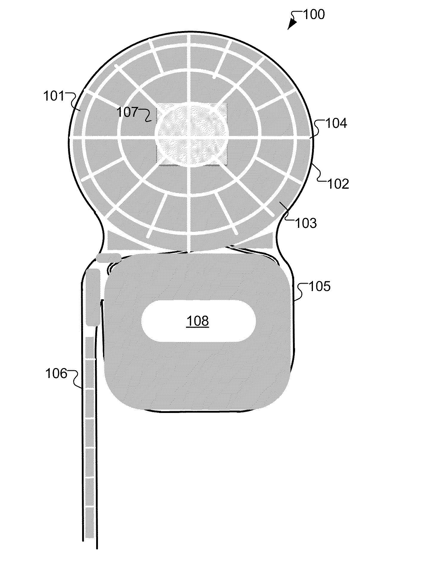
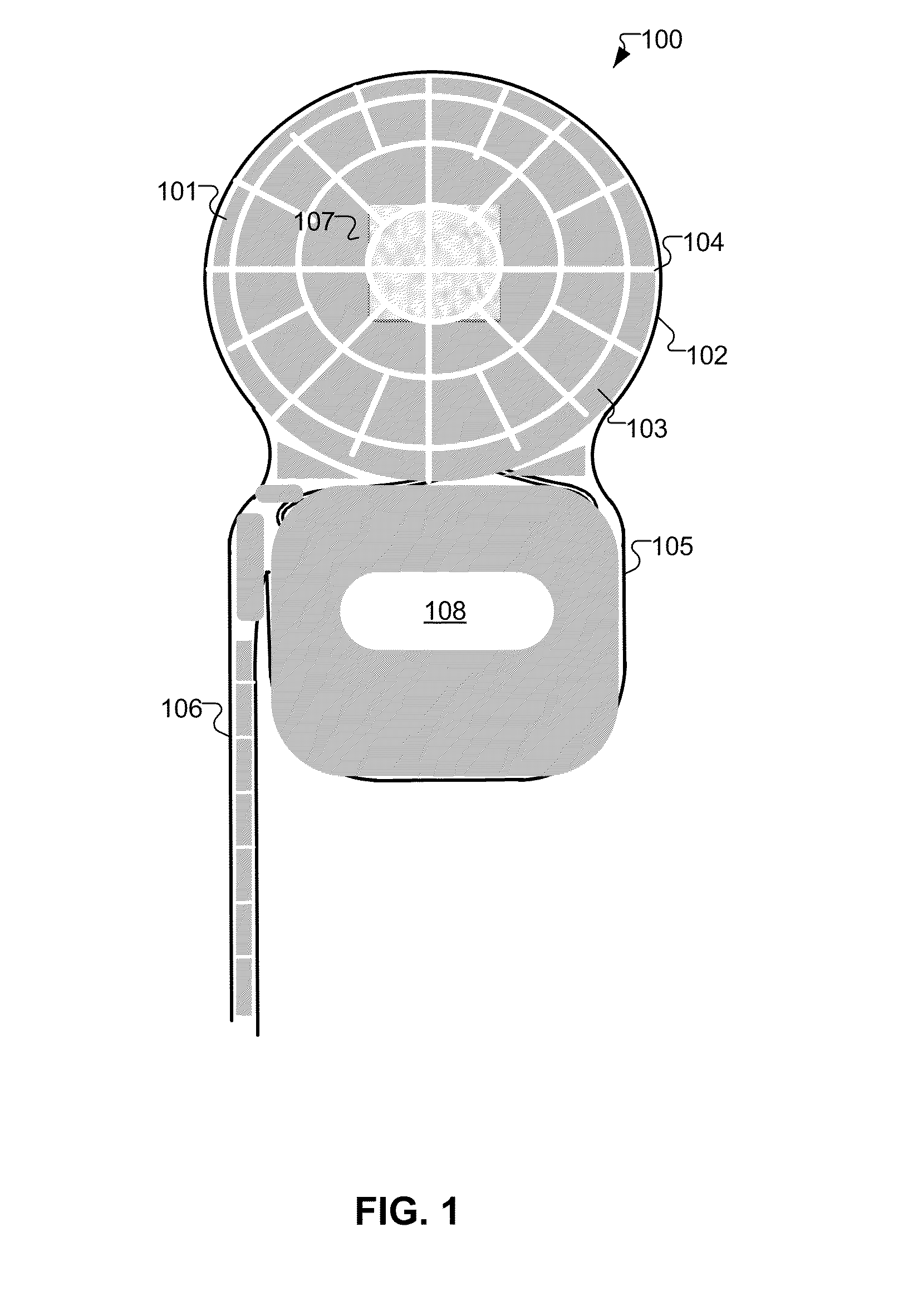
[0024]Embodiments of the present invention are directed to an implantable device that uses a surface coating and / or bulk material which are developed in a pattern that avoids many of the problems that arise in previous approaches. Some of the benefits which specific embodiments of a therapeutic surface coating may provide include, without limitation:[0025]unimpeded data and energy transfer through the inductively coupled transcutaneous link[0026]avoidance of RF-heating of the surface coating due to eddy currents (e.g. in the event of Magnetic Resonance Imaging (MRI) or even during normal use).[0027]This may be especially important during the charging phase of an implanted battery when a relatively high amount of RF power is sent over the inductive link.[0028]good back-telemetry data transfer properties.

[0029]FIG. 1 shows an implantable device 100 having a patterned conductive coating 101 according to an embodiment of the present invention. The upper circular portion is a coil housin...


PUM


Abstract

An implantable device includes an implanted coil for receiving a transcutaneous coil signal from an external transmitting coil. A coil housing contains the coil and has a non-conductive surface. A conductive coating covers at least a portion of the housing surface and forms a non-shielding pattern that minimizes interaction with the coil signal.

Description

[0001]This application claims priority from U.S. Provisional Patent Application 61 / 058,319, filed Jun. 3, 2008, which is incorporated herein by reference.FIELD OF THE INVENTION[0002]The present invention relates to medical implants, and more specifically to a surface coating for such devices.BACKGROUND ART[0003]Some implantable devices such as Cochlear Implants (CI's) transfer electrical energy and data via an inductive link through the skin. This requires that the implanted receiving coils are not electrically shielded, which would interfere with the signal transfer. For that reason, implant coils are either encapsulated by a non-metallic housing (e.g. made of ceramics) or are embedded into silicone outside the hermetic encapsulation of the electronic circuit.[0004]Just as with any surgical procedure, there is also some risk during implant surgery of postoperative infections at the surgical site. This risk is generally small and depends on several factors including hygiene standard...

Claims


Application Information

Patent Timeline
IPC IPC(8): A61F11/04A61N1/36
CPCA61N1/36032A61N2001/086A61N1/375A61N1/37211A61N1/086A61N1/36038A61N1/0541A61N1/36128
Inventor ZIMMERLING, MARTIN
Owner MED EL ELEKTROMEDIZINISCHE GERAETE GMBH
Why Eureka
Try Eureka