Mechanical thrombectomy apparatuses and methods

a thrombosis and mechanical technology, applied in the field of mechanical thrombosis apparatuses and methods, can solve the problems of insufficient or irregular blood flow, so as to prevent collapse/buckling of the catheter, prevent the collapse of the catheter, and minimize the force

Active Publication Date: 2017-03-30
STRYKER CORP
View PDF30 Cites 62 Cited by
  • Summary
  • Abstract
  • Description
  • Claims
  • Application Information

AI Technical Summary

Benefits of technology

[0013]In use, a guidewire may be configured to slide through the apparatus (and may form part of the apparatus) to allow positioning and in some variations support, typically without interfering with the operation of the tractor tube drawing an object such as a blood clot into the body of the catheter.
[0055]Any of these apparatuses may also include an outer catheter extending over the catheter and flexible tube. The outer catheter may extend over the catheter and the flexible tube and may keep an external portion of the distal tractor region (outside of the catheter) collapsed until it has been delivered. Any of these apparatuses may include a lubricious region of the flexible tube extending between a distal end of the outer catheter and the distal end opening, wherein the majority of the flexible tube is not lubricious. This lubricious region may reduce the initial force required to start actuating the apparatus.

Problems solved by technology

Many vascular system problems stem from insufficient blood flow through blood vessels.
One causes of insufficient or irregular blood flow is a blockage within a blood vessel referred to as a blood clot, or thrombus.
If one of the coronary arteries is 100% thrombosed, the flow of blood is stopped in that artery, resulting in a shortage of oxygen carrying red blood cells, e.g., to supply the muscle (myocardium) of the heart wall.
Such a thrombosis is unnecessary to prevent loss of blood but can be undesirably triggered within an artery by damage to the arterial wall from atherosclerotic disease.
Similarly, thrombosis of one of the carotid arteries can lead to stroke because of insufficient oxygen supply to vital nerve centers in the cranium.
Oxygen deficiency reduces or prohibits muscular activity, can cause chest pain (angina pectoris), and can lead to death of myocardium which permanently disables the heart to some extent.
If the myocardial cell death is extensive, the heart will be unable to pump sufficient blood to supply the body's life sustaining needs.
This procedure can take several hours and is not always successful in breaking up the thrombus.
Furthermore, it can lead to downstream thrombus fragments (emboli) which can lead to blockage of small diameter branches.
However, the device is characterized by small catheter tip size and thus is unable to exert significant total force on clot masses.
Also, a clot which is not in good position of purchase on a vessel wall in the “line of fire” of the rotating wire is not fibrinectomized.
Further disadvantages to this thrombectomy device include the difficulty of keeping the clot in the space above the wire during all degrees of rotation as the wire is moved sideways during rotation, which is sometimes necessary to sweep the arterial lumen.
In fact, sweeping out an entire arterial lumen with a rotating wire is virtually impossible in all but the smallest, i.e., less than 1.5 mm diameter, arteries.
An additional and serious possible disadvantage is that fragments of the clot may be embolized downstream.
Unfortunately, the basket occludes the inside of the lumen, preventing the concurrent use with a positioning and / or supporting guidewire, and the basket must be held in or near the distal end of the catheter.
Depending on the stiffness of the material (e.g., clot) being removed, retrieval of the basket often collapses the distal end of the catheter, preventing its use, and the basket can be difficult to pull into the catheter, particularly when holding a clot.
This may result in sheering the clot.
Finally the basket must be preloaded into the distal end of the catheter prior to insertion into the vessel, and preloading may be both difficult and time consuming, and may risk disrupting the device prior to deployment.

Method used


Image

  • Mechanical thrombectomy apparatuses and methods
  • Mechanical thrombectomy apparatuses and methods
  • Mechanical thrombectomy apparatuses and methods

Examples


Embodiment Construction

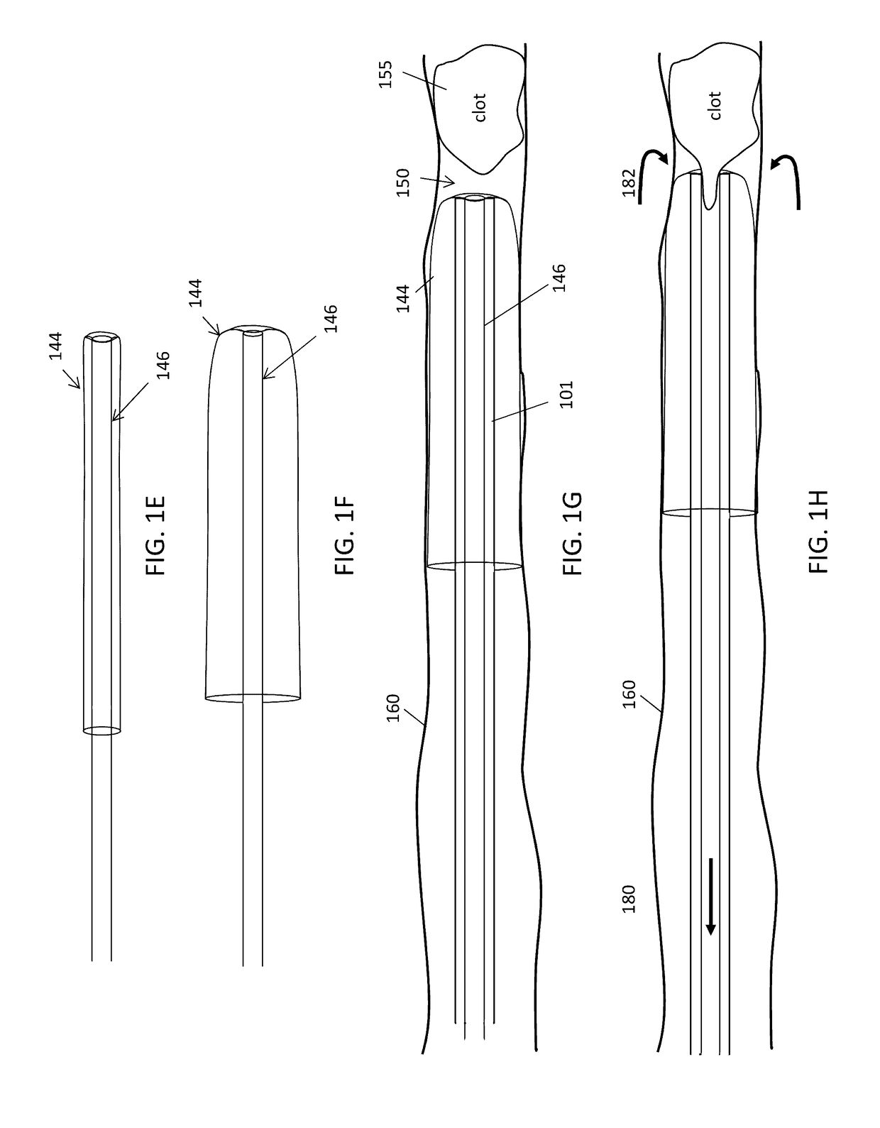
[0115]In general, described herein are methods and apparatuses for mechanically removing objects from a body. Although these methods and apparatuses may be adapted for use to remove a variety of objects from a variety of regions of the body, they may be particularly well suited for removal of blood clots from within a lumen of a blood vessel. Thus described herein are mechanical thrombectomy apparatuses (e.g., device and systems).

[0116]The apparatuses described herein (e.g., mechanical thrombectomy apparatus for removing a clot from a vessel) may be assemblies including an elongate catheter having a distal end and a distal end opening, and a flexible tractor assembly at least partially within the catheter, where the distal end region of the tractor assembly is configured as a distal tractor region that at least partially extends within the catheter and doubles back over the distal end of the catheter. The tractor assembly may include a proximate pusher region which is connected to t...


PUM


Abstract

Methods and apparatuses for mechanically removing objects from a body. In particular, described herein are thrombectomy methods and mechanical thrombectomy apparatuses for removal of blood clots from within a lumen of a blood vessel.

Description

CROSS REFERENCE TO RELATED APPLICATIONS[0001]This patent application is a continuation of U.S. patent application Ser. No. 15 / 043,996, filed Feb. 15, 2016, which claims priority to each of the following provisional patent applications: U.S. Provisional Patent Application No. 62 / 284,300, filed Sep. 28, 2015; U.S. Provisional Patent Application No. 62 / 284,752, filed Oct. 8, 2015; and U.S. Provisional Patent Application No. 62 / 245,560, filed Oct. 23, 2015 each of which is herein incorporated by reference in its entiretyINCORPORATION BY REFERENCE[0002]All publications and patent applications mentioned in this specification are herein incorporated by reference in their entirety to the same extent as if each individual publication or patent application was specifically and individually indicated to be incorporated by reference.FIELD[0003]The apparatuses and methods described herein relate to mechanical removal of objects from within a body. In particular, described herein are mechanical t...

Claims


Application Information

Patent Timeline
Patent Type & Authority Applications(United States)
IPC IPC(8): A61B17/221A61B17/00
CPCA61B17/221A61B17/00234A61B2017/00292A61B2017/00358A61B2217/005A61B2017/22038A61B2017/22079A61B2017/00862A61B2017/00867A61B2017/00778A61B17/22A61B17/22031A61B2017/22044A61B2017/2215A61B2017/306A61B2017/3435A61B10/04
Inventor GREENHALGH, E. SKOTTWALLACE, MICHAEL P.
Owner STRYKER CORP
Why Eureka
Try Eureka