Cutting apparatus and printing apparatus

a cutting apparatus and printing technology, applied in printing, metal working apparatus, other printing apparatus, etc., can solve the problems of cutting failure, uncut sheet remains, cutting failure, etc., and achieve the effect of reducing cutting time and reliably cutting a sh

Active Publication Date: 2017-03-30
CANON KK
View PDF9 Cites 11 Cited by
  • Summary
  • Abstract
  • Description
  • Claims
  • Application Information

AI Technical Summary

Benefits of technology

[0004]The present invention provides a cutting apparatus that can reliably cut a sheet even when the width of the sheet is changed while shortening cutting time, and a printing apparatus.
[0008]According to the present invention, since the position of an end portion of a sheet is detected and a cutting range is set according to the detected position of the end portion, a sheet can be reliably cut even when the width of the sheet is changed while cutting time is shortened.

Problems solved by technology

However, since the cutting apparatus disclosed in Japanese Patent Laid-Open No. 2000-317884 selects the cutting range from the plurality of cutting ranges, which are fixedly set in advance, according to the width of a sheet, there is a concern that cutting failure may occur when the width of the sheet is changed due to unexpected factors.
When a sheet of which the width has been changed as described above is cut in a preset cutting range, there is a concern that cutting failure in which an uncut portion of the sheet remains may occur.

Method used


Image

  • Cutting apparatus and printing apparatus
  • Cutting apparatus and printing apparatus
  • Cutting apparatus and printing apparatus

Examples


first embodiment

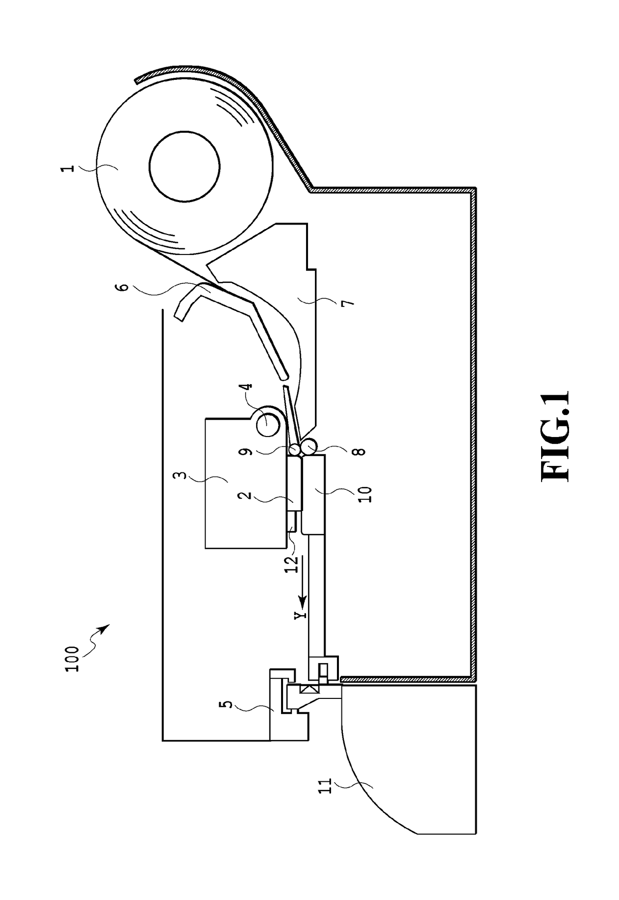
[0041]FIG. 1 is a sectional view of an ink jet printing apparatus 100 according to an embodiment of the invention. A continuous sheet 1, which is wound into a roll, is held in the printing apparatus 100, and the sheet 1 is sent through a conveying path between an upper guide 6 and a lower guide 7. The sheet 1 is held at a nip portion between a conveying roller 8 and a pinch roller 9, is conveyed in a conveying direction, which is indicated by an arrow Y, and is sent onto a platen 10 disposed at a printing position that faces a printing head 2. Images are printed on the sheet 1, which is conveyed to the printing position, with ink ejected from the printing head 2. The printing head 2, a carriage 3 for printing on which the printing head 2 is mounted, and the platen 10 that is disposed so as to face the printing head 2 form an image printing unit. A carriage shaft 4 and a guide rail (not illustrated) are disposed in the printing apparatus 100 so as to be parallel to each other, and th...

second embodiment

[0117]In the above-mentioned first embodiment, the reverse position P2 of the cutter unit 300 has been determined on the basis of information about the position of the end portion 1b, which is close to the back position and detected by the sheet end sensor 12, of the sheet 1. Information about the position of the end portion 1a, which is close to the home position, of the sheet 1 is further considered in the second embodiment. In the second embodiment, the same components as those of the first embodiment will be denoted by the same reference numerals and the description thereof will be omitted.

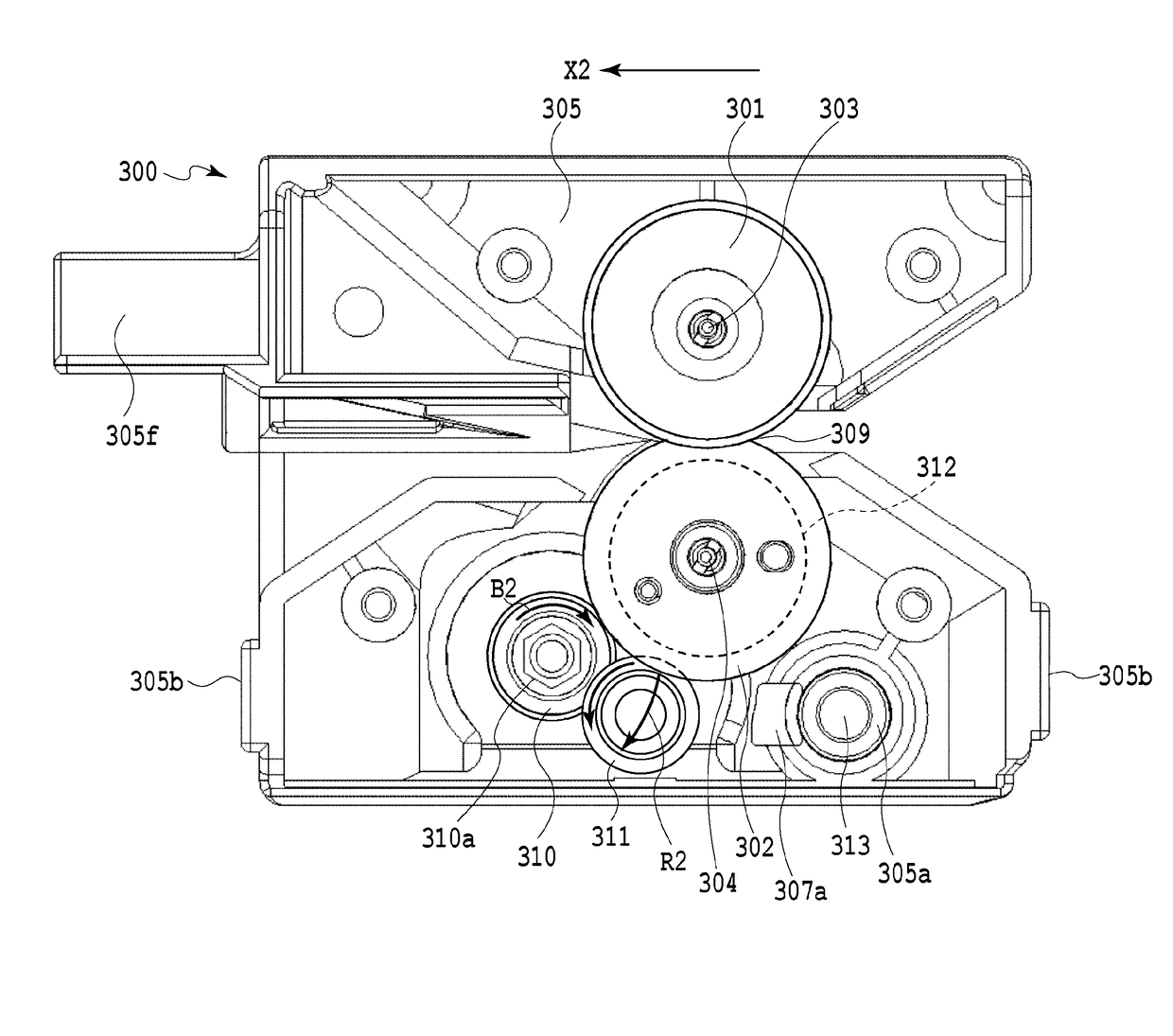
[0118]A cutting operation of the second embodiment will be described with reference to FIGS. 27 to 29. FIG. 27 is a flowchart illustrating an operation until the end of cutting from the start of printing, and FIGS. 28A, 28B, and 28C are diagrams illustrating a step of cutting a narrow sheet into the shape of a strip. FIG. 29 is a schematic diagram illustrating the cutter unit 300 at the time o...


PUM


Abstract

In order to reliably cut a sheet even when the width of the sheet is changed while shortening cutting time, the position of an end portion of the sheet is sensed and a cutting range is set according to the sensed position of the end portion.

Description

BACKGROUND OF THE INVENTIONField of the Invention[0001]The present invention relates to a cutting apparatus that can cut a sheet and a printing apparatus including the cutting apparatus.Description of the Related Art[0002]Japanese Patent Laid-Open No. 2000-317884 discloses a recording apparatus that sets a plurality of cutting ranges of a sheet to be cut by a cutting apparatus and switches the cutting ranges according to the width of a sheet in order to shorten cutting time.[0003]However, since the cutting apparatus disclosed in Japanese Patent Laid-Open No. 2000-317884 selects the cutting range from the plurality of cutting ranges, which are fixedly set in advance, according to the width of a sheet, there is a concern that cutting failure may occur when the width of the sheet is changed due to unexpected factors. Examples of factors, which cause the width of the sheet to change, include the expansion of a sheet, such as paper, which is caused by changes in temperature and humidity,...

Claims


Application Information

Patent Timeline
Patent Type & Authority Applications(United States)
IPC IPC(8): B41J11/70B41J2/01
CPCB41J2/01B41J11/70B26D1/08B26D1/185B26D1/245B26D5/32
Inventor KIKUCHI, TETSUOWAKAYAMA, NAOKIMASUDA, SHUICHINAGASHIMA, MASAKAZUANAYAMA, DAIKIOHASHI, TAKAKAZU
Owner CANON KK
Why Eureka
Try Eureka