Agricultural working vehicle transmission combination

Active Publication Date: 2017-03-30
DAEDONG IND
View PDF1 Cites 8 Cited by
  • Summary
  • Abstract
  • Description
  • Claims
  • Application Information

AI Technical Summary

Benefits of technology

[0029]According to the present invention, the transmission assembly for an agricultural work vehicle is configured wherein the flywheel housing covering the engine flywheel is formed unitarily with the clutch housing and the spare space in the housings and the case is effectively utilized to allow the respective units to fee efficiently located therein, thereby satisfying the demand in the market for a large gear-shifting range and achieving both of miniaturization and compactness of the product.
[0030]As the miniaturizatio

Problems solved by technology

However, the conventional transmission assembly for the agricultural work vehicle is complicated in structure, thereby causing high manufacturing costs and low assemblability and productivity, and is bulky in whole

Method used


Image

  • Agricultural working vehicle transmission combination
  • Agricultural working vehicle transmission combination
  • Agricultural working vehicle transmission combination

Examples


Example

[0042]Hereinafter, an explanation on a transmission assembly for an agricultural, work vehicle according to the present invention will be in detail given with reference to the attached drawing. In the description, if it is determined that the detailed explanation on the well known technology related to the present invention, makes the scope of the present invention not clear, the explanation will be avoided for the brevity of the description.

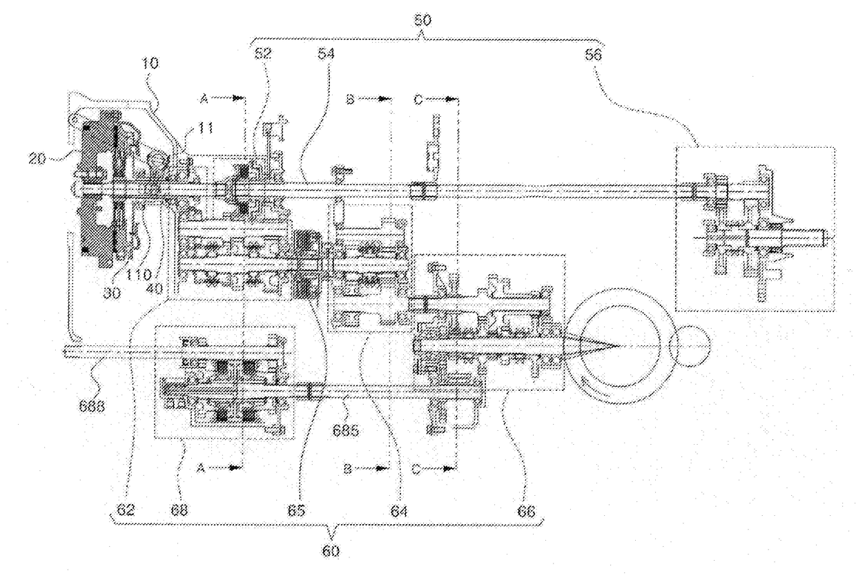
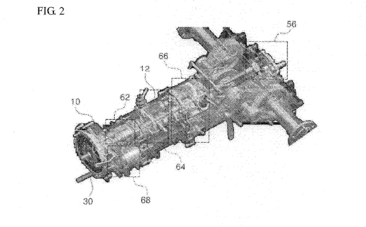
[0043]FIG. 2 is a perspective view showing a transmission assembly for an agricultural work vehicle according to the present invention, and FIG. 3 is a development view showing the transmission assembly for an agricultural work vehicle according to the present invention. First, the whole configuration of a transmission assembly for an agricultural work vehicle according to the present invention will be described with reference to FIGS. 2 and 3.

[0044]In the description, all of gears, which are rotated unitarily with shafts and rotated freely ther...


PUM


Abstract

An agricultural working vehicle transmission combination includes: a clutch housing having a flywheel housing integrally formed thereon so as to cover an engine flywheel and a hollow transmission case directly connected to the rear side of the clutch housing. The clutch housing includes a PTO clutch unit for connecting/disconnecting transfer of engine power to a PTO shaft, a main gear-shifting unit for primary gear-shifting of engine power, and a bi-speed turn unit for front-wheel bi-speed turn execution. The transmission case includes a forward/backward gear-shifting unit connected to the rear side of the main gear-shifting unit via an intermediate clutch such that power can be transferred and a sub gear-shifting unit for secondary gear-shifting behind the forward/backward gear-shifting unit.

Description

TECHNICAL FIELD[0001]The present invention relates to a transmission assembly for an agricultural work vehicle, and more particularly, to a transmission assembly for an agricultural work vehicle that is adapted to change the power generated from an engine to a torque needed for driving or working and to transmit the torque.BACKGROUND ART[0002]An agricultural work vehicle which is called ‘tractor’ is structurally similar to general cars, but it has a powerful engine so that it has good traction force and is strong. As a result, the tractor is generally used for cultivation in agricultural work, and so as to perform the cultivation, further, the tractor has various kinds of agricultural work machines detachable attached to the rear side of the body thereof.[0003]So as to improve the efficiencies of the work, the agricultural work vehicle has to have a large gear-shifting range so that a driving speed and a rotational speed of a power take off (which is referred to as ‘PTO’) shaft can ...

Claims


Application Information

Patent Timeline
IPC IPC(8): B60K17/28F16H57/02B60K17/06B60K25/06F16H3/091
CPCB60K17/28B60K25/06F16H2003/0822B60K17/06F16H57/02F16H3/091B60Y2200/22B60Y2200/221F16H37/043
Inventor PARK, DONG WOOKSHIN, KI SUNG
Owner DAEDONG IND
Why Eureka
Try Eureka