Hydraulic cylinder for aircraft landing gear

Active Publication Date: 2017-03-30
SUMITOMO PRECISION PROD CO LTD
View PDF12 Cites 5 Cited by
  • Summary
  • Abstract
  • Description
  • Claims
  • Application Information

AI Technical Summary

Benefits of technology

[0011]The snubbing mechanism is configured to, when the piston approaches the end of the stroke, allow the valve that moves with the piston to close the open supply/discharge port to form the throttle oil pas

Problems solved by technology

If, while the hydraulic cylinder is being used, the throttle oil passages are clogged with foreign matter in hydraulic oil, a hydraulic oil discharge passage is blocked at the end of the stroke, thereby impairing the functioning of the hydraulic cylinder.
Since the snubber ring having the slits slides over the inner circumferential surface of the cylinder tube, wear

Method used


Image

  • Hydraulic cylinder for aircraft landing gear
  • Hydraulic cylinder for aircraft landing gear
  • Hydraulic cylinder for aircraft landing gear

Examples


Embodiment Construction

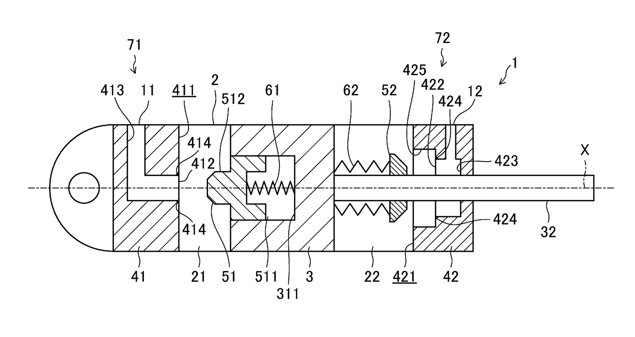
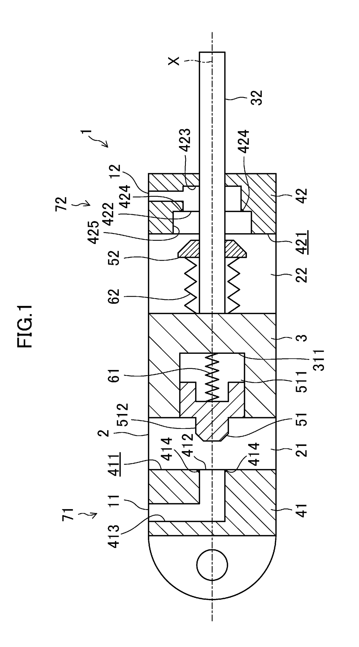
[0020]Specifically, the present disclosure relates to a hydraulic cylinder for an aircraft landing gear. This hydraulic cylinder includes: a cylinder tube; a piston configured to define oil chambers in the cylinder tube; a piston rod connected to the piston; a pair of end covers provided at ends of the cylinder tube, and configured to each define an end of a stroke of the piston; and a snubbing mechanism configured to reduce a moving speed of the piston after the piston approaches the end of the stroke.

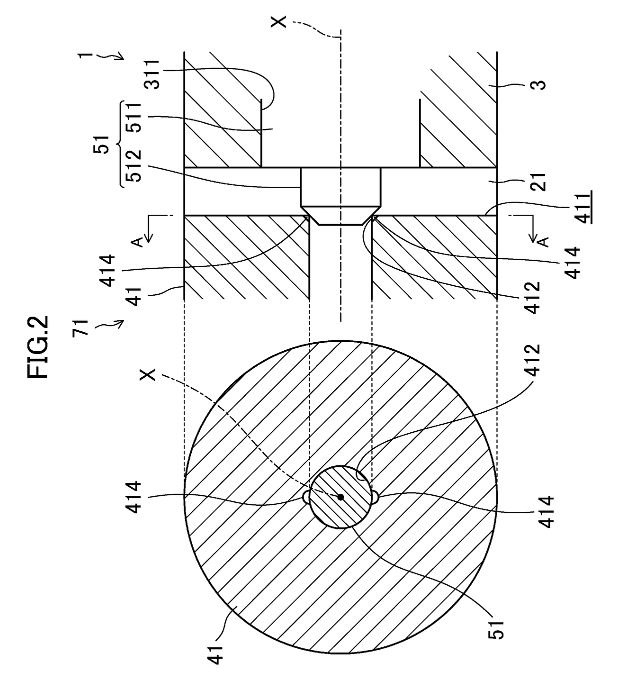
[0021]The snubbing mechanism includes: a supply / discharge port which is provided in an associated one of the end covers so as to be oriented in a direction of the stroke of the piston and communicate with an associated one of the oil chambers, and through which hydraulic oil is supplied and discharged into and from the associated oil chamber; a valve configured to open and close the supply / discharge port in the associated oil chamber; a connector configured to connect the valve and th...


PUM


Abstract

A hydraulic cylinder includes: a cylinder tube; a piston; a piston rod; a pair of end covers; and a snubbing mechanism configured to reduce the moving speed of the piston after the piston reaches the vicinity of the end of its stroke. The snubbing mechanism includes: a supply/discharge port formed in an associated one of the end covers; a valve configured to open and close the supply/discharge port; a connector configured to connect the valve and the piston together; and at least one recess extending from the edge of the supply/discharge port. When the piston approaches the end of its stroke, the valve closes the supply/discharge port to form a throttle oil passage, and hydraulic oil is discharged through the throttle oil passage to reduce the moving speed of the piston.

Description

CROSS-REFERENCE TO RELATED APPLICATION[0001]This application claims priority to and full benefit of Japanese Patent Application No. 2015-194249, filed on Sep. 30, 2015, the entire disclosure of which as is hereby incorporated by reference herein.BACKGROUNDRelated Field[0002]The present disclosure relates to a hydraulic cylinder for an aircraft landing gear.Description of Related Art[0003]United States Patent Application Publication No. 2011 / 107756 A1 describes a hydraulic cylinder for an aircraft landing gear. This hydraulic cylinder includes a cylinder tube, a piston, and a snubbing mechanism. The piston defines oil chambers in the cylinder tube, and reciprocates by supplying and discharging hydraulic oil into and from the oil chambers. After the piston approaches the end of its stroke, the snubbing mechanism reduces the moving speed of the piston to reduce shock generated when the piston reaches the end of its stroke.[0004]The snubbing mechanism includes a supply / discharge port wh...

Claims


Application Information

Patent Timeline
IPC IPC(8): B64C25/22F15B15/14F15B15/22
CPCB64C25/22F15B15/1433F15B15/1447F15B15/226F15B15/227
Inventor KONDO, TAKUONISHI, TAKAAKIHAGIHARA, SHOGO
Owner SUMITOMO PRECISION PROD CO LTD
Why Eureka
Try Eureka