Scroll compressor and method of manufacturing the same
a compressor and roller technology, applied in the direction of machines/engines, rotary/oscillating piston pump components, liquid fuel engines, etc., can solve the problems of power loss and increase of oil loss, and achieve the effect of preventing agitation of surrounding fluid and preventing an increase in vibration
- Summary
- Abstract
- Description
- Claims
- Application Information
AI Technical Summary
Benefits of technology
Problems solved by technology
Method used
Image
Examples
embodiment 1
[0022]The following first describes the structure of a scroll compressor 100 according to the present Embodiment 1.
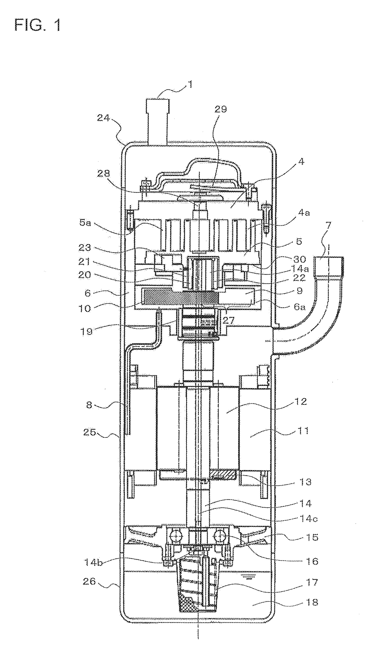
[0023]FIG. 1 is a vertical sectional view of the scroll compressor 100 according to Embodiment 1 of the present invention.
[0024]The scroll compressor 100 is configured to suck and compress refrigerant circulating in a refrigeration cycle, and discharge the refrigerant at high temperature and high pressure. As illustrated in FIG. 1, the scroll compressor 100 includes a compression mechanism unit and an electric motor unit in a shell, where the compression mechanism unit is arranged on an upper side, and the electric motor unit is arranged on a lower side.
[0025]The shell is a pressure resisting container including a middle shell 25 having a cylinder shape, a lower shell 26 sealed to an opening on a lower surface of the middle shell 25 by, for example, welding, and an upper shell 24 sealed to an upper surface opening of the middle shell 25 by, for example, welding.
[0026]Th...
embodiment 2
[0052]The following describes the present Embodiment 2. Any description duplicating with that in Embodiment 1 will be omitted, and any part identical or equivalent to that in Embodiment 1 will be denoted by the same reference numeral.
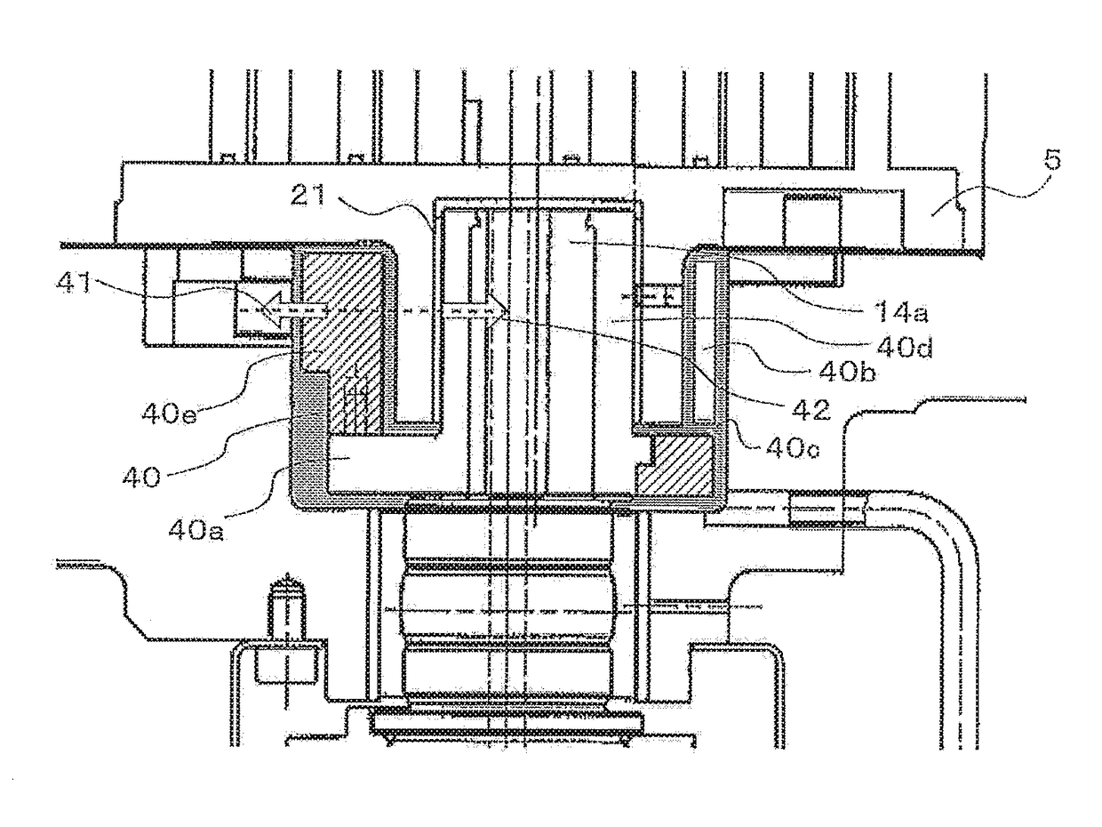
[0053]FIG. 4 is an enlarged view of the vicinity of a balancer-attached slider ASSY 40 of the scroll compressor 100 according to Embodiment 2 of the present invention. FIGS. 5(a) and 5(b) are each a diagram illustrating the balancer-attached slider ASSY 40 of the scroll compressor 100 according to Embodiment 2 of the present invention. FIG. 5(a) is a side view of the balancer-attached slider ASSY 40, and FIG. 5(b) is a sectional view taken along line B-B in FIG. 5(a).
[0054]In the present Embodiment 2, the compression mechanism unit is provided with the balancer-attached slider ASSY 40. The balancer-attached slider ASSY 40 includes a balancer-attached slider 40a in which a slider 40d is attached to a high-density balancer 40f, and a low-density part 40b ...
embodiment 3
[0058]The following describes the present Embodiment 3. Any description duplicating with that in Embodiment 1 will be omitted, and any part identical or equivalent to that in Embodiment 1 will be denoted by the same reference numeral.
[0059]FIG. 7 is a vertical sectional view of the scroll compressor 100 according to Embodiment 3 of the present invention.
[0060]In the present Embodiment 3, as illustrated in FIG. 7, the second balancer 13 includes a high-density part 52 and a low-density part 51 having a density lower than that of the high-density part 52.
[0061]Even when the scroll compressor 100 is operated while refrigerant is accumulated and the second balancer 13 is immersed in a mixture of liquid refrigerant and oil, the oil and the liquid refrigerant do not flow into the second balancer 13, causing no difference in centrifugal force of the second balancer 13 from a designed value, and preventing an increase in vibration.
[0062]FIGS. 8(a) and 8(b) are each a diagram illustrating a ...
PUM
 Abstract
Description
Claims
Application Information
 - R&D
- Intellectual Property
- Life Sciences
- Materials
- Tech Scout
- Unparalleled Data Quality
- Higher Quality Content
- 60% Fewer Hallucinations
Browse by: Latest US Patents, China's latest patents, Technical Efficacy Thesaurus, Application Domain, Technology Topic, Popular Technical Reports.
© 2025 PatSnap. All rights reserved.Legal|Privacy policy|Modern Slavery Act Transparency Statement|Sitemap|About US| Contact US: help@patsnap.com


