Parameter update method, parameter update apparatus, and non-transitory recording medium storing program for parameter update

Active Publication Date: 2017-03-30
BROTHER KOGYO KK
View PDF0 Cites 9 Cited by
  • Summary
  • Abstract
  • Description
  • Claims
  • Application Information

AI Technical Summary

Benefits of technology

[0014]According to the aspect of the present disclosure, since the evaluation function includes the second function, the value of the variable parameter which minimizes the output value of the evaluation function is calculated so as not to greatly change the characteristics of the transfer function. In particular, according to the aspect of the present disclosure, the value of the variable parameter which minimizes the output value of the evaluation function is calculated so as not to greatly change the charact

Problems solved by technology

The conventional automatic adjustment technologies, unfortunately, merely adjust the parameter of the controller to obtain a control output corresponding to the target response, and thus a contr

Method used


Image

  • Parameter update method, parameter update apparatus, and non-transitory recording medium storing program for parameter update
  • Parameter update method, parameter update apparatus, and non-transitory recording medium storing program for parameter update
  • Parameter update method, parameter update apparatus, and non-transitory recording medium storing program for parameter update

Examples


Example

First Embodiment

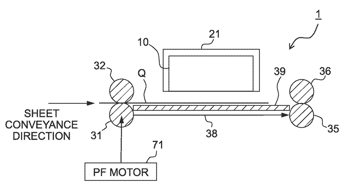
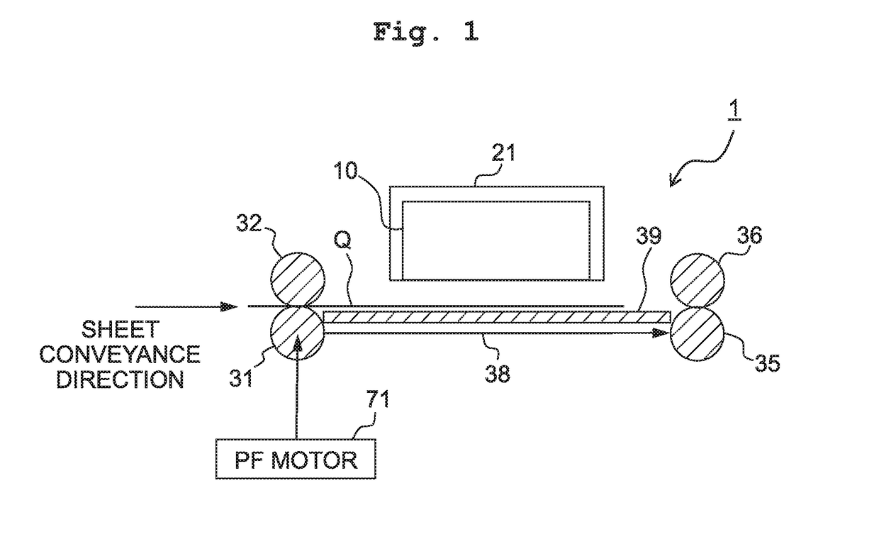
[0034]An image forming system 1 depicted in FIG. 1 is formed as an ink-jet printer. The image forming system 1 includes a recording head 10 which jets liquid droplets of ink on the sheet Q to form an image thereon. The recording head 10 is carriage on a carriage 21. The carriage 21 reciprocates in a main scanning direction (the normal direction of a sheet surface of FIG. 1) perpendicular to a sheet conveyance direction to move the recording head 10 in the main scanning direction.

[0035]Similar to known ink-jet printers, the image forming system 1 intermittently conveys the sheet Q below the recording head 10 by a predetermined amount by repeatedly performing the conveyance control of the sheet Q in which the sheet Q is conveyed by the predetermined amount and then stopped. When the sheet Q is being stopped, the carriage 21 moves in the main scanning direction and the recording head 10 jets liquid droplets of ink. Accordingly, an image in the main scanning direction is...

Example

Second Embodiment

[0093]An explanation will be made about the image forming system 1 according to the second embodiment. The image forming system 1 of the second embodiment is formed similarly to the image forming system 1 of the first embodiment, except that the evaluation function used in the parameter update unit 49 of the first embodiment is changed from the evaluation function J1 to an evaluation function J2 on the basis of the VRFT approach. Thus, the following selectively describes the configuration related to the evaluation function J2.

[0094]The parameter update unit 49 of this embodiment calculates an appropriate value of the variable parameter ρ for the position controller 83 by calculating the value of the variable parameter ρ which minimizes the next evaluation function J2, and sets the calculated value in the position controller 83.

J2=∥U−U*∥2+∥G(ρ)∥2  Formula 16

U*=C(ρ)·(T−1·Y−Y)  Formula 17

[0095]Y, U included in the evaluation function J2 are similar to Y, U included in ...


PUM


Abstract

There is provided a method of updating a setting value of a variable parameter, the method including: obtaining a time-series data of control input and a time-series data of control output observed in control with a controller; calculating a value of the variable parameter which minimizes an output value of an evaluation function based on the obtained time-series data of the control input and the control output; and updating the setting value of the variable parameter to the calculated value of the variable parameter. The evaluation function includes a first function part in which a first norm or a second norm changes depending on the value of the variable parameter, and a second function part of which specific frequency band has an amount, by which the output value of the evaluation function is increased, larger than that of any other frequency band.

Description

CROSS REFERENCE TO RELATED APPLICATION[0001]The present application claims priority from Japanese Patent Application No. 2015-194530 filed on Sep. 30, 2015, the disclosure of which is incorporated herein by reference in its entirety.BACKGROUND[0002]Field of the Invention[0003]The present disclosure relates to a parameter update method and a parameter update apparatus.[0004]Description of the Related Art[0005]As conventional automatic adjustment technologies for controllers, there are known the Fictitious Reference Iterative Tuning (FRIT) approach and the Virtual Reference Feedback Tuning (VRFT) approach. These technologies adjust a parameter of the controller so that the parameter approximates a target response.SUMMARY[0006]The conventional automatic adjustment technologies, unfortunately, merely adjust the parameter of the controller to obtain a control output corresponding to the target response, and thus a control system may become unstable. Namely, the automatic adjustment of th...

Claims


Application Information

Patent Timeline
IPC IPC(8): G05B17/02G06F17/11
CPCG06F17/11G05B17/02G05B13/024
Inventor TAKAHASHI, EISUKE
Owner BROTHER KOGYO KK
Why Eureka
Try Eureka