Grooved backing plate for standing wave compensation

a standing wave compensation and backing plate technology, applied in the direction of coatings, chemical vapor deposition coatings, electric discharge tubes, etc., can solve the problems of uniform plasma processing, increased problems, and increased problems,

Active Publication Date: 2017-03-30
APPLIED MATERIALS INC
View PDF3 Cites 299 Cited by
  • Summary
  • Abstract
  • Description
  • Claims
  • Application Information

AI Technical Summary

Benefits of technology

[0009]Implementations described herein generally relate to components and methods used in plasma processing, and more specifically relate to grooved surfaces for controlling RF return path lengths in plasma processing chambers and methods for forming the same. In one implementation, a backing plate for a plasma processing chamber is provided. The backing plate comprises a recta

Problems solved by technology

With large area plasma processing equipment, problems with plasma processing uniformity may arise when the RF frequency is higher than 13.56 MHz and a large size (large surface) substrate is used.
The problem may be exacerbated when the largest dimension of the plasma reactor (the diagonal) is equal or larger than the f

Method used


Image

  • Grooved backing plate for standing wave compensation
  • Grooved backing plate for standing wave compensation
  • Grooved backing plate for standing wave compensation

Examples


Embodiment Construction

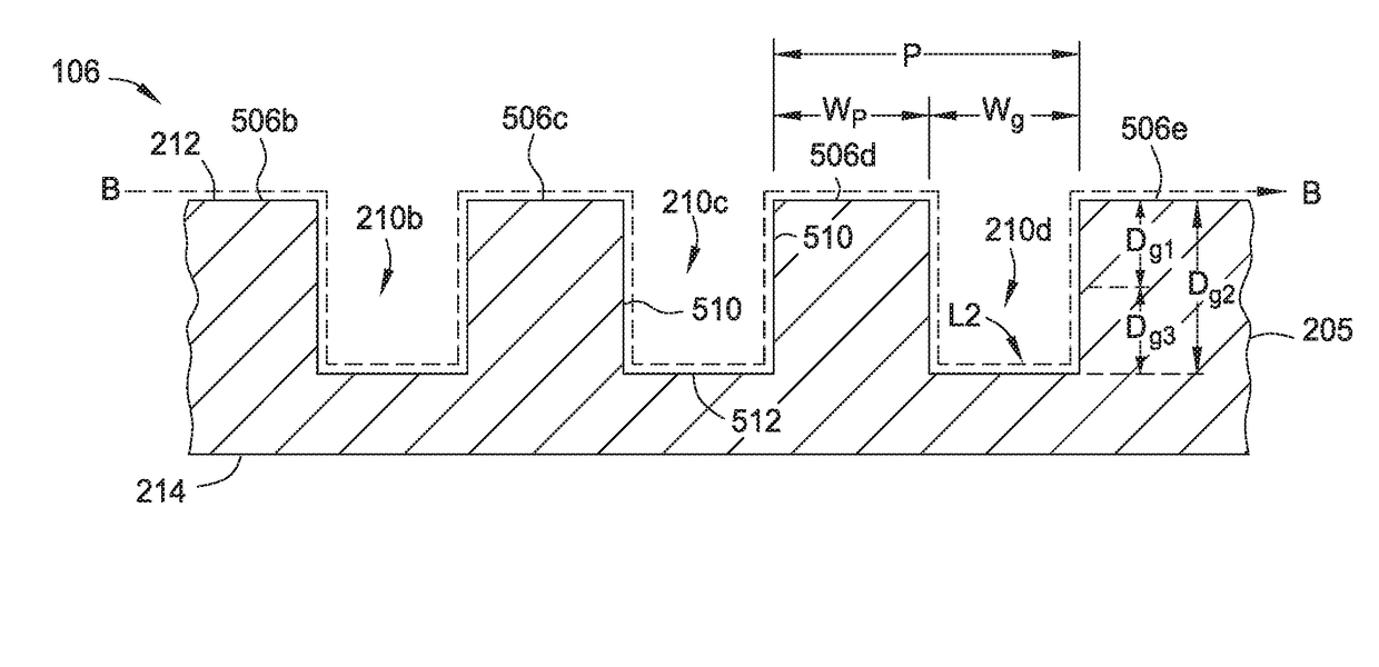
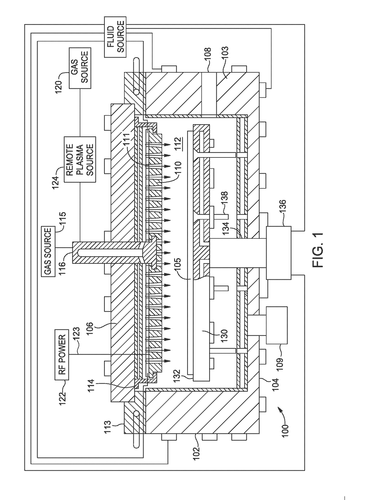
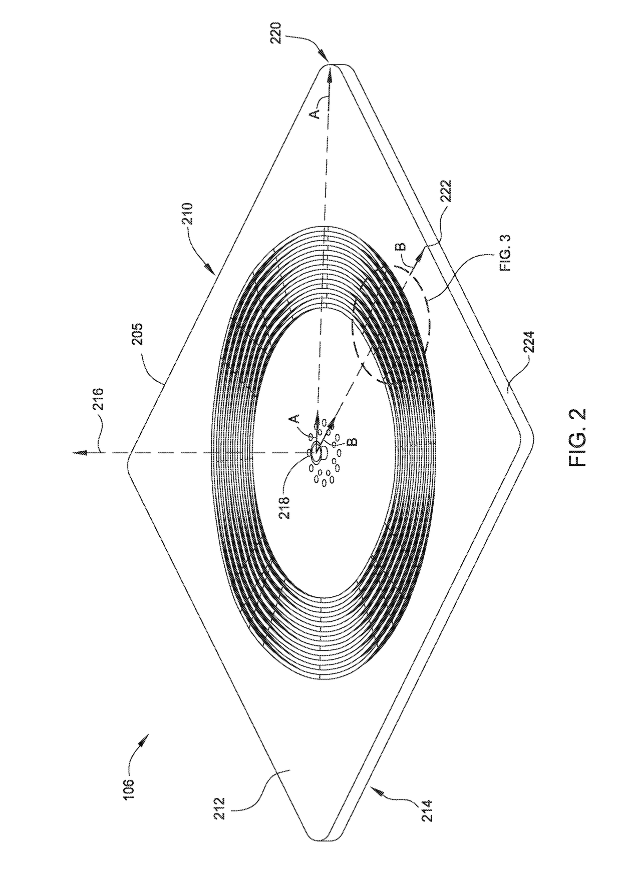
[0020]The following disclosure describes components and methods used in plasma vapor deposition to compensate for the standing wave effect. Certain details are set forth in the following description and in FIGS. 1-6 to provide a thorough understanding of various implementations of the disclosure. Other details describing well-known structures and systems often associated with plasma vapor deposition and standing wave effect compensation are not set forth in the following disclosure to avoid unnecessarily obscuring the description of the various implementations.

[0021]Many of the details, dimensions, angles and other features shown in the Figures are merely illustrative of particular implementations. Accordingly, other implementations can have other details, components, dimensions, angles and features without departing from the spirit or scope of the present disclosure. In addition, further implementations of the disclosure can be practiced without several of the details described bel...


PUM

PropertyMeasurementUnit
Lengthaaaaaaaaaa
Widthaaaaaaaaaa
Depthaaaaaaaaaa

Abstract

Implementations described herein generally relate to components and methods used in plasma processing, and more specifically relate to grooved surfaces for controlling RF return path lengths in plasma processing chambers and methods for forming the same. In one implementation, a backing plate for a plasma processing chamber is provided. The backing plate comprises a rectangular body. The rectangular body has a front surface, a back surface opposing the front surface, a first axis perpendicular to a center of the rectangular body and a plurality of grooves formed in the front surface. At least one groove of the plurality of grooves has a first length across the groove in a first location and a second length across the groove in a second location.

Description

CROSS-REFERENCE TO RELATED APPLICATIONS[0001]This application claims benefit of U.S. provisional patent application Ser. No. 62 / 232,825, filed Sep. 25, 2015. The aforementioned priority patent application is herein incorporated by reference in its entirety.BACKGROUND[0002]Field[0003]Implementations described herein generally relate to components and methods used in plasma processing of substrates, and more specifically relate to grooved surfaces for controlling RF return path lengths in plasma processing chambers and methods for forming the same.[0004]Description of the Related Art[0005]Plasma enhanced chemical vapor deposition (PECVD) is generally employed to deposit thin films on substrates, such as organic light emitting diode (OLED) substrates and semiconductor substrates. PECVD is generally accomplished by introducing a precursor gas into a vacuum chamber having a substrate disposed on a substrate support. The precursor gas is typically directed through a gas distribution showe...

Claims


Application Information

Patent Timeline
IPC IPC(8): H01J37/32C23C16/458C23C16/505
CPCH01J37/32431C23C16/505H01J2237/3321C23C16/458H01J37/321H01J37/32091H01J37/32174H01J37/32183H01J37/32568C23C16/5096
Inventor KURITA, SHINICHITINER, ROBIN L.
Owner APPLIED MATERIALS INC
Why Eureka
Try Eureka