

Connection structure and input/output connection structure of semiconductor microwave generator for microwave oven, and microwave oven
- Summary
- Abstract
- Description
- Claims
- Application Information
AI Technical Summary
Benefits of technology
Problems solved by technology
Method used
Image

Examples
Embodiment Construction
[0107]In order to give a clearer understanding of the above objects, features and advantages of the present invention, the present invention will be further described in detail below in conjunction with the accompanying drawings and specific embodiments. It needs to be noted that the embodiments of the present application and the features in the embodiments can be combined with one another without conflict.
[0108]Many specific details are elaborated in the following descriptions to make the present invention adequately understandable. However, the present invention may also be implemented in other ways than those described herein; therefore, the protection scope of the present invention is not limited by the specific embodiments disclosed below.
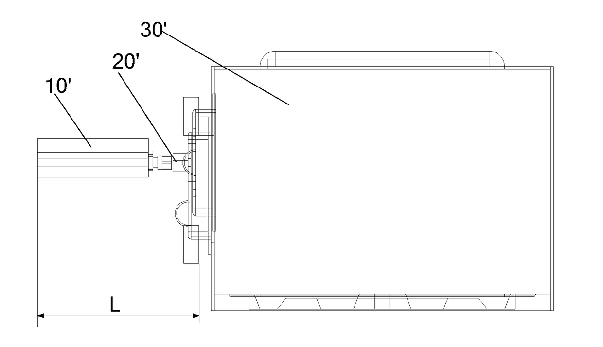
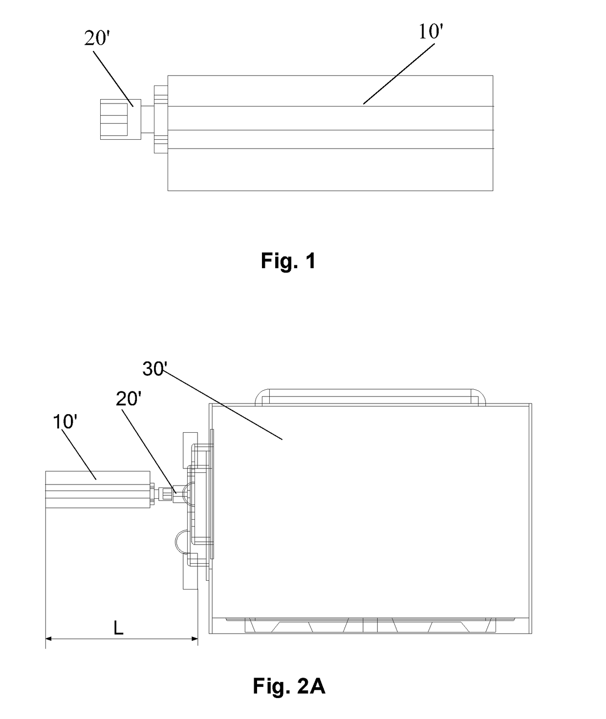
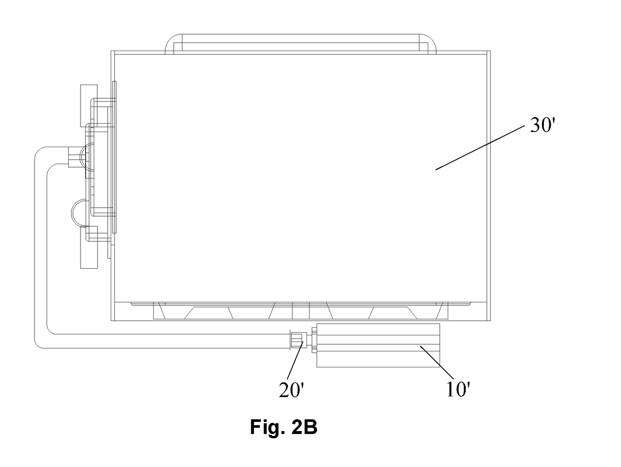
[0109]A connection structure of a semiconductor microwave generator for a microwave oven provided by some embodiments in the first aspect of the present invention is described below with reference to FIGS. 1 to 12.
[0110]As shown in FIGS. 1, 9 ...
PUM
 Abstract
Description
Claims
Application Information