Insertion tool for implant and methods of use

a technology of implant insertion and tool, which is applied in the direction of spinal implants, medical science, surgery, etc., can solve the problems of reducing the risk of neurologic injury, and achieve the effect of convenient use for surgeons

Active Publication Date: 2017-04-13
INST FOR MUSCULOSKELETAL SCI & EDUCATION
View PDF2 Cites 67 Cited by
  • Summary
  • Abstract
  • Description
  • Claims
  • Application Information

AI Technical Summary

Benefits of technology

[0011]An easy-to-use, multi-component system for insertion of an intervertebral implant and methods of use thereof are described herein. The system includes an inserter, one or more jaws for securing an implant to the system, one or more rams, and optionally, an adjustable stop. Additional components for insertion and / or removal of the implant may be included.
[0014]An adjustable stop can be attached onto the superior portion of the outer surface of the inserter body. The adjustable stop is attached in a manner that allows for rapid, tool free control over the depth of insertion of an implant in a patient's spine.

Problems solved by technology

Although the anterior lumbar approach involves retracting (moving out of the way, temporarily) large blood vessels (aorta, vena cava) and the intestines, there is a wide exposure of the intervertebral disc without retraction of the spinal nerves and neurologic structures (and therefore, a decreased risk of neurologic injury).

Method used


Image

  • Insertion tool for implant and methods of use
  • Insertion tool for implant and methods of use
  • Insertion tool for implant and methods of use

Examples


Embodiment Construction

I. Insertion System

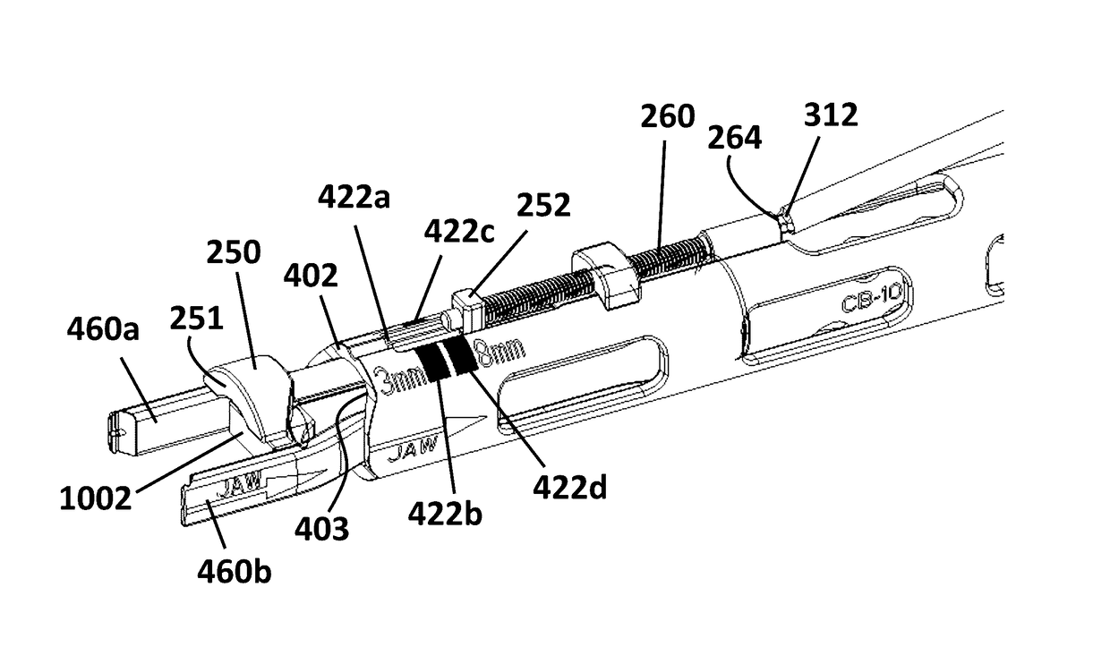
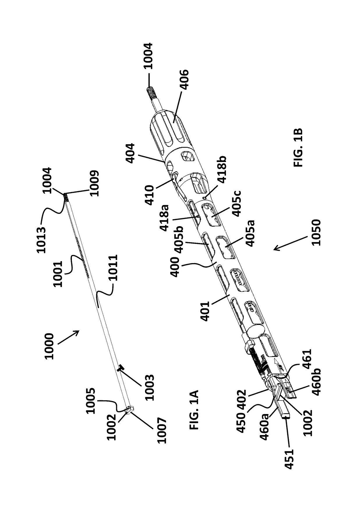
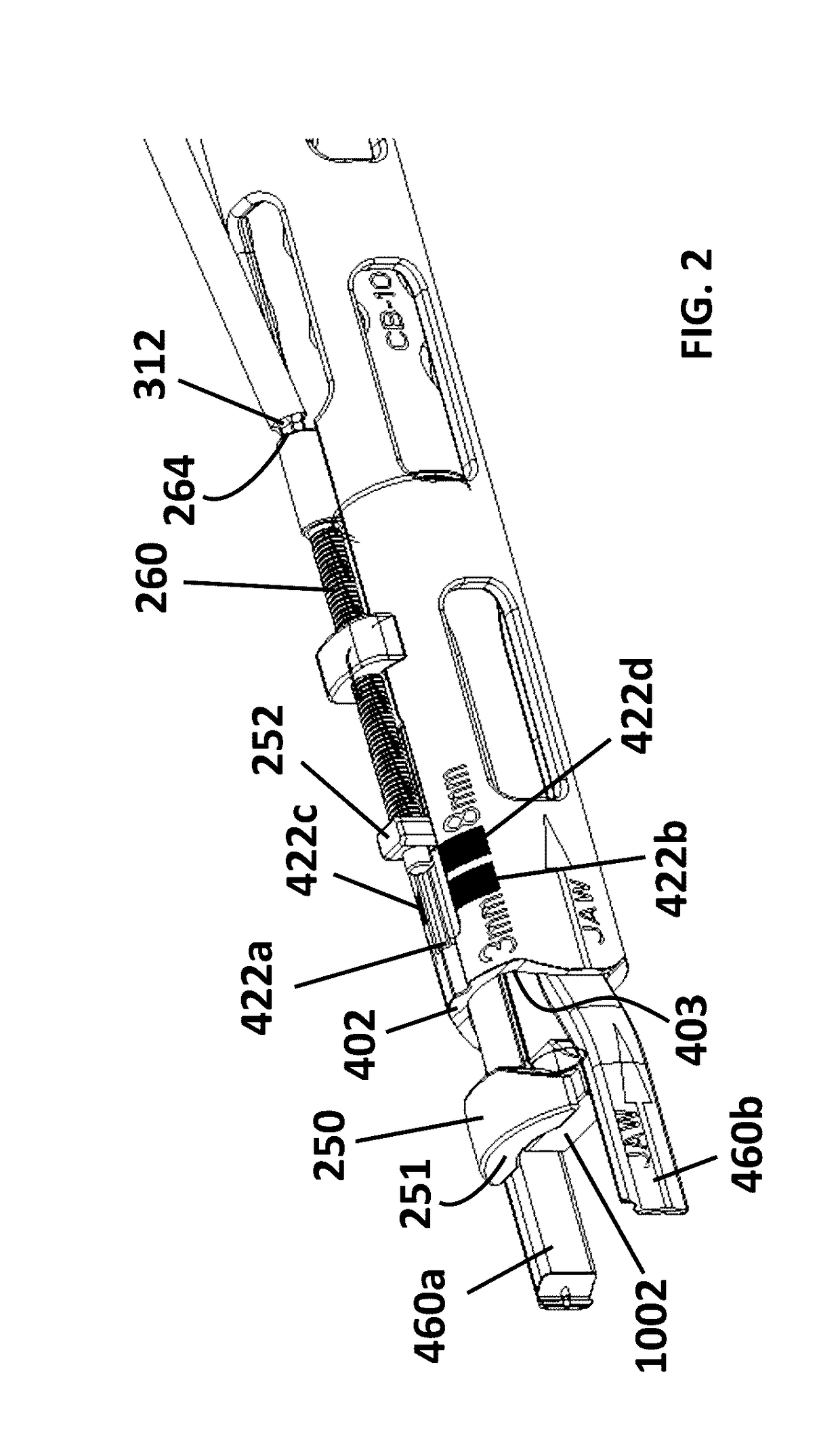
[0039]The insertion system (1050, 1500) contains an inserter, a jaw, a ram and optionally, an adjustable stop. Additional components may be attached to one or more parts of the insertion system, as needed.

[0040]The inserter is configured to receive the jaw, ram and adjustable stop, each of which are removable from the inserter.

[0041]A. Inserter

[0042]Exemplary inserters (400, 800) suitable for anterior and / or lateral insertion are illustrated in FIGS. 1B and 7. The inserter has a body (401, 817) with a hollow central cavity (403, 801) running along a central axis. The body has a superior surface (817), a distal end (402, 802) and a proximal end (404, 804), with a knob (406, 806) that is attached to the proximal end (404, 804) of the inserter in a manner that allows for free rotation of the knob. The knob may be attached to the proximal end (404, 804) by any suitable means, such as for example by a pin connection of the knob (406) to the proximal end (404) of the in...


PUM


Abstract

A multi-component implant insertion system for insertion of an intervertebral implant cage and methods of use thereof are described herein. Preferably, the proximal end of a hollow jaw is inserted into the distal end of an inserter. Once inside the inserter, a thread on the jaw engages a corresponding thread inside the inserter, allowing axial advancement of the jaw along the inserter. A ram is inserted through the proximal end of the jaw until the distal end of the ram protrudes at the distal end of the inserter assembly. Optionally, an adjustable stop introduced onto the superior portion of the inserter allows for control over the depth of insertion of the implant. An implant of appropriate size is introduced to the jaw of the inserter assembly and the implant / inserter assembly can be impacted into the vertebral body until the adjustable stop contacts the anterior edge of the vertebral body.

Description

CROSS-REFERENCE TO RELATED APPLICATION[0001]This application claims priority to U.S. Ser. No. 62 / 240,447, filed Oct. 12, 2015, the disclosure of which is incorporated herein in its entirety by reference.FIELD OF THE INVENTION[0002]The present invention generally relates to lumbar interbody fusions, and particularly to methods and systems for guiding and delivering implants into the spine.BACKGROUND OF THE INVENTION[0003]Anterior lumbar interbody fusion (ALIF) is a type of spinal fusion that utilizes an anterior (front—through the abdominal region) approach to fuse the lumbar spine bones together. The intervertebral disc is removed and replaced with a spacer. The anterior technique is often used when multiple spinal levels are being fused and multiple discs need to be removed. ALIF may be performed in conjunction with or without a posterior decompression (laminectomy) and / or instrumentation (use of metal crews / rods). The anterior approach is also used when only one spinal level is fu...

Claims


Application Information

Patent Timeline
Patent Type & Authority Applications(United States)
IPC IPC(8): A61F2/46A61F2/44
CPCA61F2/4611A61F2/4455A61B2017/922A61B2090/062A61F2002/4662A61B2090/034A61F2002/4622A61F2002/4681A61F2/442A61F2002/4627A61F2002/4629A61B2090/036A61F2/4603
Inventor DUFFIELD, WILLIAMSACK, JAMES A.
Owner INST FOR MUSCULOSKELETAL SCI & EDUCATION
Why Eureka
Try Eureka