Suspension control device for vehicle

a suspension control and vehicle technology, applied in the direction of vehicle components, suspensions, transportation and packaging, etc., can solve the problems of force applied from the road surface to the vehicle body via, and the vibration of the vehicle body caused by this force cannot be effectively decreased

Active Publication Date: 2017-04-13
TOYOTA JIDOSHA KK
View PDF0 Cites 24 Cited by
  • Summary
  • Abstract
  • Description
  • Claims
  • Application Information

AI Technical Summary

Benefits of technology

[0011]The present disclosure has a primary object to improve the control of the actuator configured to change the up / down stroke of the suspension, thereby decreasing the force applied from the road surface to the vehicle body via the wheel and the vibration of the vehicle body caused by the force when the wheel passes over roughness such as a step.

Problems solved by technology

Thus, the force applied from the road surface to the vehicle body via the wheel and a vibration of the vehicle body caused by this force cannot effectively be decreased.

Method used


Image

  • Suspension control device for vehicle
  • Suspension control device for vehicle
  • Suspension control device for vehicle

Examples


first embodiment

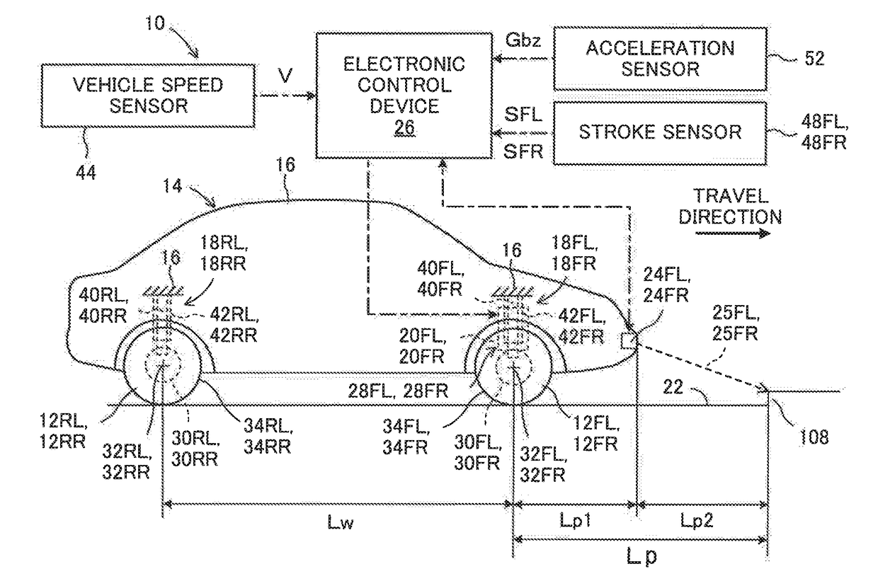
[0041]FIG. 1 and FIG. 2 are respectively a side view and a plan view for illustrating an overview of a suspension control device 10 for a vehicle according to a first embodiment of the present disclosure. As illustrated in those diagrams, the suspension control device 10 is applied to a vehicle 14 including front left and right wheels 12FL and 12FR, which are steered wheels, and rear left and right wheels 12RL and 12RR, which are non-steered wheels. The vehicle 14 includes front wheel suspensions 18FL and 18FR for respectively suspending the front wheels 12FL and 12FR from a vehicle body 16, and rear wheel suspensions 18RL and 18RR for respectively suspending the rear wheels 12RL and 12RR from the vehicle body 16.

[0042]In the following, when a plurality of wheels and members provided for a plurality of wheels are generally referred to, letters such as FL for identifying a specific wheel are omitted. For example, as a term for generally referring to the front wheels 12FL and 12FR and...

first modified example

[0093]FIG. 6 is a flowchart for illustrating a control routine for the actuator in the suspension control device 10 for a vehicle according to a first modified example of the present disclosure. In FIG. 6, the same steps as the steps illustrated in FIG. 5 are denoted by the same step numbers as that assigned in FIG. 5.

[0094]As appreciated from a comparison between FIG. 6 and FIG. 5, Steps 10 to 30 and Steps 60 to 90 are carried out as in the first embodiment. When the affirmative determination is made in Step 30, Step 40 is carried out before Step 50, resulting in a correction of the radius R of the wheel 12.

[0095]According to the first modified example, signals indicating air pressures PtFL and PtFR of the tires 34FL and 34FR of the wheels 12FL and 12FR detected by tire air pressure sensors, not shown in FIG. 1, are input to the electronic control device 26. Moreover, signals indicating wheel speeds VwFL and VwFR of the wheels 12FL and 12FR detected by wheel speed sensors, not show...

second modified example

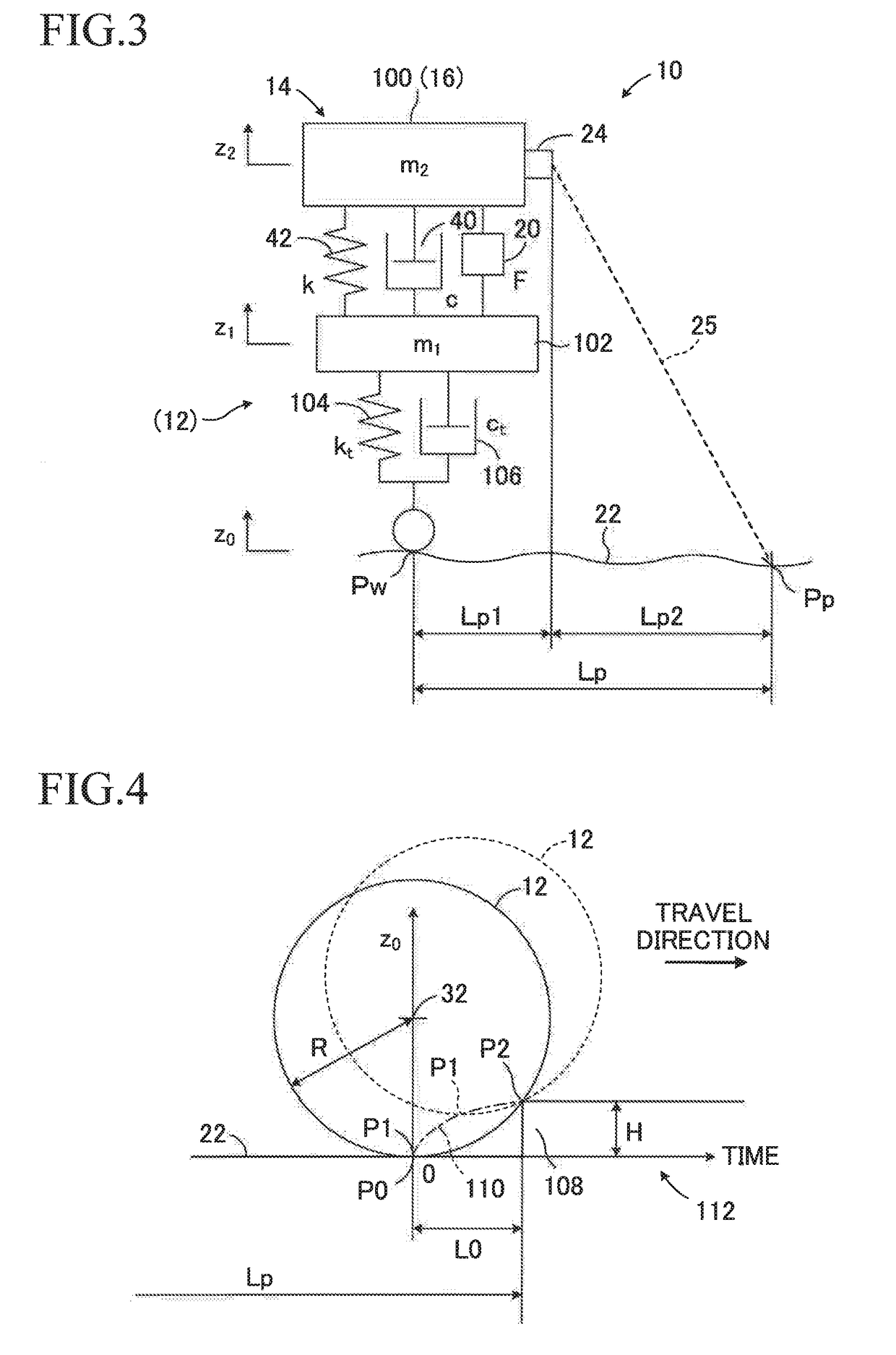
[0100]FIG. 7 is a diagram for illustrating the movement of the wheel 12 when the air pressure Pt of the tire 34 of the wheel 12 is low, and the tire 34 is thus in contact with the road surface 22 in a contact region having a relatively wide area, and is contact with the step portion 108. The lowest point P0 and the point P1 are points directly below the rotational axis 32 of the wheel 12 out of the contact region of the tire 34 viewed in a lateral direction of the vehicle.

[0101]In FIG. 7, a virtual line represents a virtual wheel 12p when the rotational axis 32 is at the same position as that of the rotational axis 32 of the wheel 12 represented as the solid line, and the air pressure Pt of the tire 34 is the standard air pressure Pt0. The lowest point P0 of the virtual wheel 12p is denoted by a virtual lowest point Pp0, and a distance in the vertical direction between the lowest point P0 and the virtual lowest point Pp0 is denoted by zc. A point of the corner of a step portion 108p...


PUM


Abstract

A suspension control device includes an actuator configured to change an up / down stroke of a suspension, a front sensor, and a control device configured to estimate a displacement in a vertical direction of a road surface based on a detection result of the front sensor, thereby controlling the actuator. When the control device determines that a step portion in which a wheel comes into contact with two points of the road surface viewed in a direction along a rotational axis of the wheel exists ahead of a vehicle, the control device controls a force generated by the actuator so that, when the wheel comes into contact with the two points, the wheel rolls about the point without substantially pressing the point toward the travel direction of the vehicle.

Description

CROSS-REFERENCE TO RELATED APPLICATIONS[0001]The disclosure of Japanese Patent Application No. JP 2015-199605 filed on Oct. 7, 2015 is incorporated herein by reference in its entirety.BACKGROUND[0002]1. Technical Field[0003]The present disclosure relates to a suspension control device for a vehicle, e.g., a motor vehicle.[0004]2. Description of the Related Art[0005]As a suspension of a vehicle, there is known a suspension including an actuator for controlling an up / down stroke of the suspension or a force applied to the suspension. As a control device for this type of the suspension, there is known a control device for predicting an undulation of a road surface ahead of the vehicle, estimating a displacement in a vertical direction of the road surface based on a result of the prediction, and controlling the actuator so that the up / down stroke of the suspension changes depending on the displacement in the vertical direction of the road surface.[0006]For example, in Japanese Patent Ap...

Claims


Application Information

Patent Timeline
Patent Type & Authority Applications(United States)
IPC IPC(8): B60G17/0165B60G17/016
CPCB60G17/0165B60G17/0161B60G2600/182B60G2500/30B60G2400/82B60G2400/10B60G2400/204B60G2400/252B60G2500/20
Inventor TSUDA, TAISHI
Owner TOYOTA JIDOSHA KK
Why Eureka
Try Eureka