Wheelie suppressing device

a technology of suppressing device and wheelie, which is applied in the direction of electrical control, ignition automatic control, tractors, etc., can solve the problems of difficult rapid reduction of engine output, and achieve the effect of quick suppression of wheeli

Active Publication Date: 2017-04-13
KAWASAKI MOTORS LTD
View PDF0 Cites 5 Cited by
  • Summary
  • Abstract
  • Description
  • Claims
  • Application Information

AI Technical Summary

Benefits of technology

[0007]An object of the present invent

Problems solved by technology

Therefore, it is difficult to r

Method used


Image

  • Wheelie suppressing device
  • Wheelie suppressing device
  • Wheelie suppressing device

Examples


embodiment 1

Vehicle

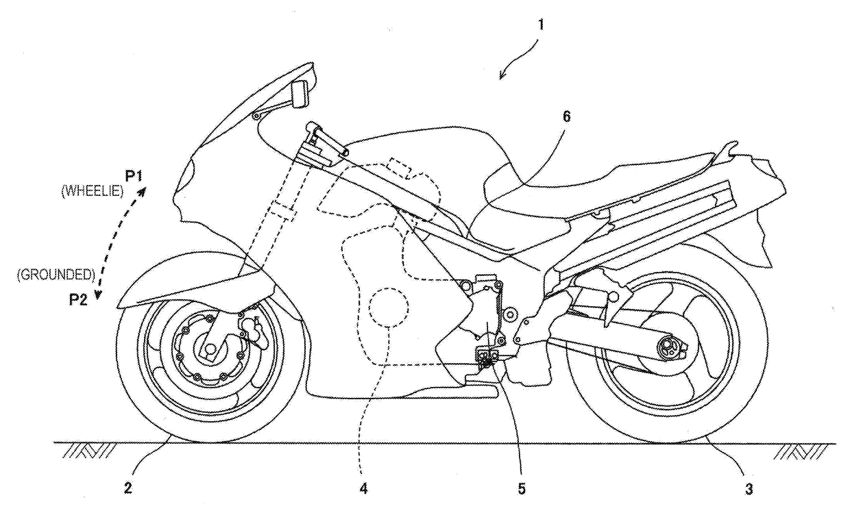
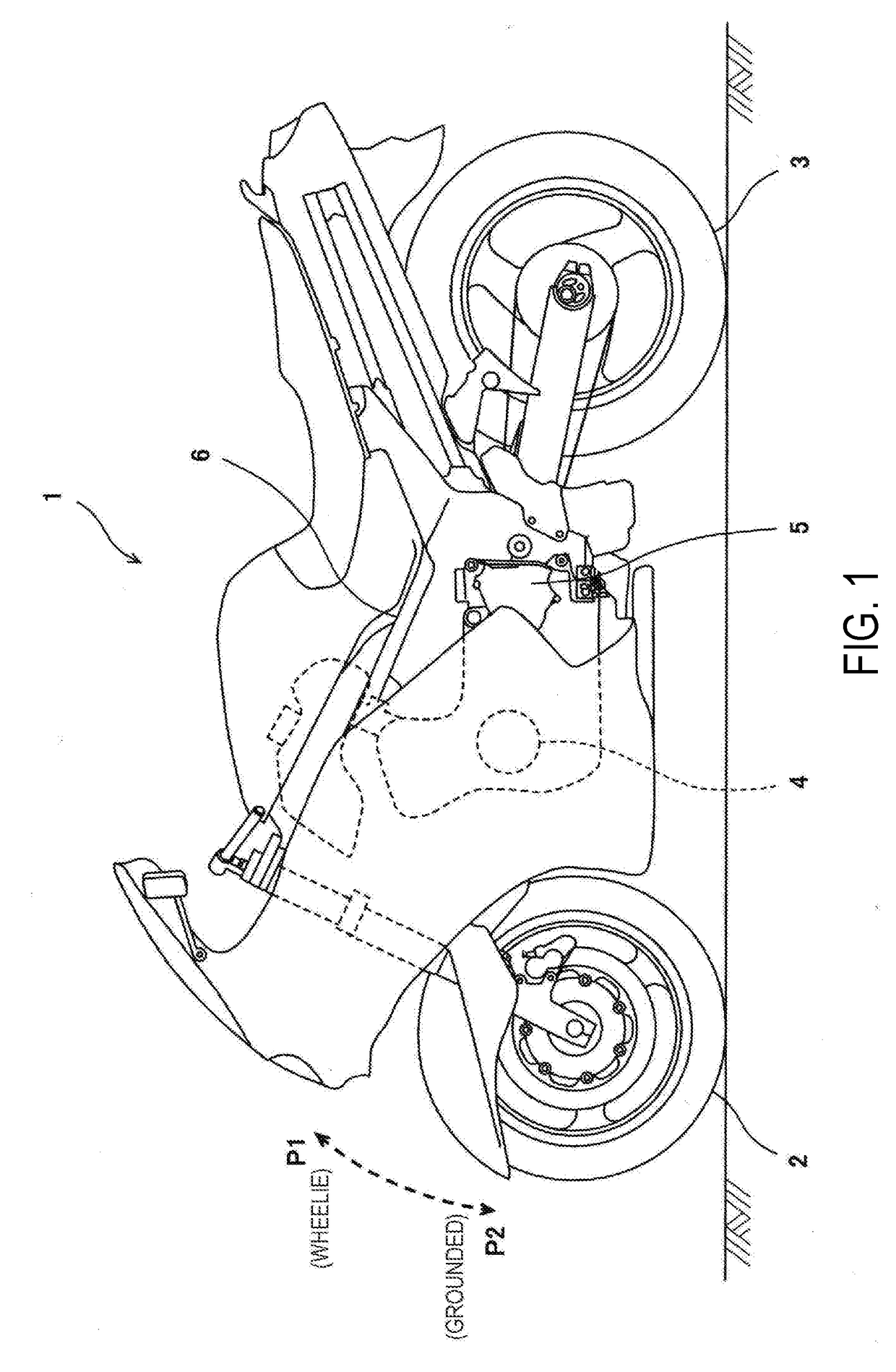
[0029]As shown in FIG. 1, a vehicle 1 includes a front wheel 2, a rear wheel 3, and an engine 4. Driving power generated by the engine 4 is transmitted to the rear wheel 3 via a driving power transmission mechanism 5. A motorcycle which is exemplarily shown as the vehicle 1 includes one front wheel 2 and one rear wheel 3. A wheel base between the front wheel 2 and the rear wheel 3 is small, and a power-to-weight ratio [W / g] is high. For this reason, a lift-off of the front wheel 2 from a ground surface, namely, a wheelie tends to occur in the motorcycle. Therefore, the motorcycle is a suitable example of the vehicle 1 including a wheelie suppressing control 10 (see FIG. 2).

[0030]While the engine output is great, and great driving power is transmitted from the engine 4 to the rear wheel 3 (drive wheel), the wheelie tends to occur. Therefore, while the wheelie is occurring in the vehicle 1, the rotational speed and rotational acceleration rate of the rear wheel 3, and the groun...

embodiment 2

[0082]FIG. 6 is a view showing an engine air-intake system according to Embodiment 2. As shown in FIG. 6, in Embodiment 2, an electronic throttle valve device 58 includes a main valve 58a and a sub-valve 58b provided together with the main valve 58a. Each of the main valve 58a and the sub-valve 58b includes valve elements which are rotatable within an air-intake passage. The valve elements of the main valve 58a and the valve elements of the sub-valve 58b are arranged in series within the air-intake passage. For example, the sub-valve 58b is disposed upstream of the main valve 58a in an intake-air flow direction. The main valve 58a is mechanically coupled via a wire to the acceleration operation unit which can be operated by the rider. The main valve 58a is opened and closed in response to the rider's throttle operation (operation of the acceleration operation unit). The sub-valve 58b is opened and closed in such a manner its opening degree is electronically controlled, as in the ele...


PUM


Abstract

A wheelie suppressing device comprises a wheelie determiner section which detects a wheelie state; and a wheelie suppressing section which performs a wheelie suppressing control for suppressing an engine output when the wheelie determiner section has detected the wheelie state, wherein the wheelie suppressing control includes a first suppressing control for suppressing the engine output while performing fuel feeding and an ignition operation, and a second suppressing control for suppressing the engine output by performing the fuel feeding or the ignition operation at a reduced rate.

Description

CROSS-REFERENCE TO RELATED APPLICATION[0001]This application claims priority to and the benefit of Japanese Patent Application No. 2015-199421 filed on Oct. 7, 2015, the entire disclosure of which is incorporated herein by reference.BACKGROUND OF THE INVENTION[0002]Field of the Invention[0003]The present invention relates to a wheelie suppressing device which can suppress a wheelie occurring in a vehicle, by suppressing the output of a drive source.[0004]Description of the Related Art[0005]An engine output control device disclosed in JP2010-229912A is configured to reduce an engine output by increasing a retard amount of an ignition timing and an opening degree reduction amount of a throttle valve with an increase in a vehicle body pitch angle in a state in which a wheelie is occurring in a vehicle.[0006]However, in an ignition retard control, an air-fuel mixture is combusted inside a cylinder. For this reason, it is difficult to increase the reduction amount of the engine output. I...

Claims


Application Information

Patent Timeline
IPC IPC(8): B60K28/10F02P5/145F02D37/02F02D9/08F02D41/30F02D41/00
CPCB60K28/10F02D41/3005F02D41/0002F02D37/02F02D2200/50F02P5/145B60Y2200/12B60Y2400/3032B60Y2400/301F02D9/08F02D9/1095F02D41/0087F02D41/021F02D2250/26F02P5/045F02P5/1504F02P5/1512F02P9/002Y02T10/40
Inventor HIROKAMI, TATSUYATERAI, SHOHEIAZUMA, SEIJIUEDA, KENGO
Owner KAWASAKI MOTORS LTD
Why Eureka
Try Eureka