

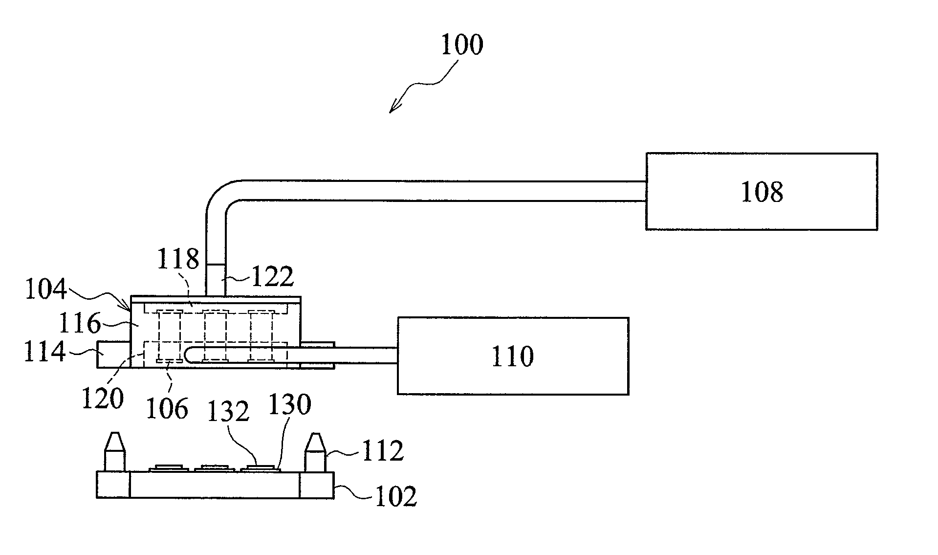
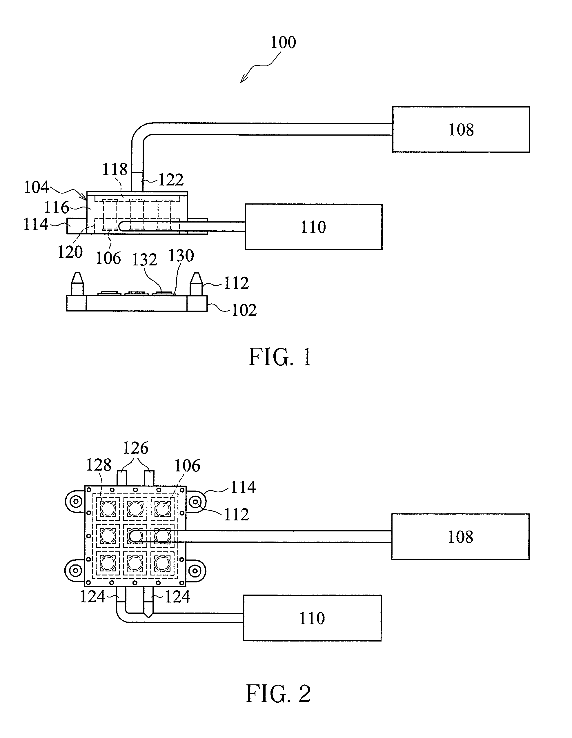
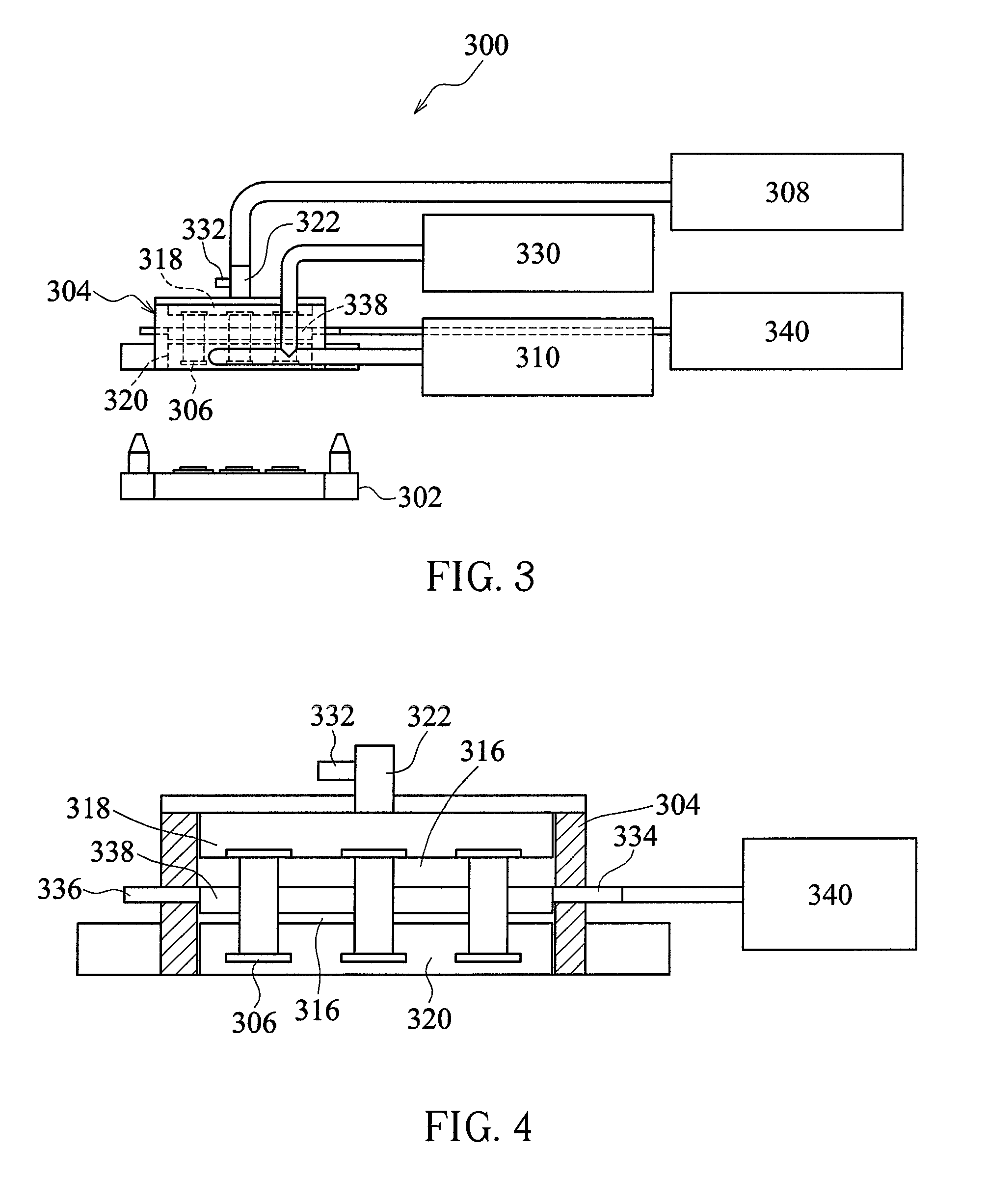
Device and method for chip pressing
a technology of pressing device and chip, applied in the direction of presses, manufacturing tools, controlling lamination, etc., can solve the problems of complex mechanism, inability to uniformly and fast heat or cool a chip and a carrier, and difficult to achieve uniform heat or cooling. uniform and fast heat or cooling, the effect of fast pressing process
- Summary
- Abstract
- Description
- Claims
- Application Information
AI Technical Summary
Benefits of technology
Problems solved by technology
Method used
Image

Examples
Embodiment Construction
[0019]For the following defined terms, these definitions shall be applied, unless a different definition is given in the claims or elsewhere in this specification. All numeric values are herein defined as being modified by the term “about,” whether or not explicitly indicated. The term “about” generally refers to a range of numbers that a person of ordinary skill in the art would consider equivalent to the stated value to produce substantially the same properties, function, result, etc.
[0020]A numerical range indicated by a low value and a high value is defined to include all numbers subsumed within the numerical range and all subranges subsumed within the numerical range. As an example, the range 10 to 15 includes, but is not limited to, 10, 10.1, 10.47, 11, 11.75 to 12.2, 12.5, 13 to 13.8, 14, 14.025, and 15.
[0021]The term “gas” herein denotes any gas or mixture thereof applicable to a conventional package process.
[0022]The term “chip” herein denotes any type of chips applicable t...
PUM
| Property | Measurement | Unit |
|---|---|---|
| pressure | aaaaa | aaaaa |
| temperature | aaaaa | aaaaa |
| temperature | aaaaa | aaaaa |
Abstract
Description
Claims
Application Information