Arrangement for double break contact with electro-magnetic arc-blow

a double break contact and electro-magnetic arc blowing technology, applied in the direction of circuit-breaking switch contacts, circuit-breaking switch for excess current, circuit-breaking switch, etc., can solve the problem of breaker tripping, affecting the operation of the circuit interrupter, becoming a very serious issue, etc., and achieve the effect of quick suppression of an ar

Active Publication Date: 2019-03-19
CARLING TECH
View PDF6 Cites 3 Cited by
  • Summary
  • Abstract
  • Description
  • Claims
  • Application Information

AI Technical Summary

Benefits of technology

[0013]What is desired then is a circuit interrupter that is adapted for use with high voltage applications and quickly suppresses an arc that forms between the contacts.
[0015]It is still further desired to provide a circuit interrupter that can be used in high voltage applications that minimizes the formation of an arc forming between the contacts.

Problems solved by technology

If a fault condition, such as a power surge occurs in the electrical wiring, the breaker will trip.
This will cause a breaker that was in an “on” position to flip to an “off” position and interrupt the flow of electrical power through the breaker.
A problem with the above-described circuit interrupters arises when energized contacts are opened while under load.
This can become a very serious issue in high voltage applications.
The creation of an arc during transition of the contacts can result in undesirable effects that negatively affect the operation of the circuit interrupter, even potentially creating a safety hazard.
These negative effects can also have adverse consequences on the functioning of the circuit interrupter.
One possible consequence is that the arc may short to objects inside the circuit interrupter and / or to surrounding objects, causing damage and presenting a potential fire or safety hazard.
Another consequence of arcing is that the arc energy damages the contacts themselves, causing some material to escape into the air as fine particulate matter.
The debris that has been melted off of the contacts can migrate or be flung into the mechanism of the circuit interrupter, destroying the mechanism or reducing its operational lifespan.
Still another effect of arcing is due to the extremely high temperature of the arc (tens of thousands of degrees Celsius), which can impact the surrounding gas molecules creating ozone, carbon monoxide, and other dangerous compounds.

Method used


Image

  • Arrangement for double break contact with electro-magnetic arc-blow
  • Arrangement for double break contact with electro-magnetic arc-blow
  • Arrangement for double break contact with electro-magnetic arc-blow

Examples


Embodiment Construction

[0034]Referring now to the drawings, wherein like reference numerals designate corresponding structure throughout the views.

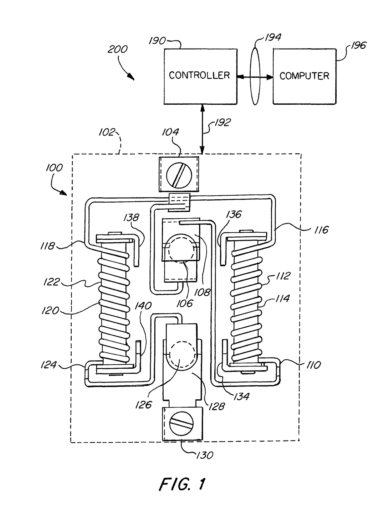
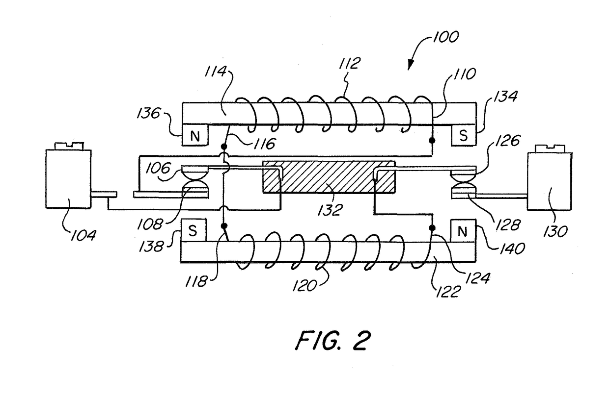
[0035]Reference is now made to FIGS. 1 and 2 where FIG. 1 is provides a view of high voltage switching system 200 including a top view of circuit interrupter 100. FIG. 2 provides a side view of certain elements of circuit interrupter 100.

[0036]The circuit interrupter 100 includes a housing 102 within which the working elements are maintained. The circuit interrupter 100 includes a line terminal 104, which is adapted to be connected to a source of electrical power (not shown). Line terminal 104 is electrically connected to a first moveable contact 106. Also provided is a first stationary contact 108, which together with the first moveable contact 106 form a first set of contacts.

[0037]The first stationary contact 108 is electrically connected to a second end 110 of a first winding 112, which is wrapped around a first core 114. A second end 116 of the first windi...


PUM


Abstract

A high voltage switch system including a circuit interrupter having a first set of contacts in series with a first coil, which are in series with a second coil and a second set of contacts, the first coil wound around a first core and the second coil wound around a second coil such that upon an arc forming between the contacts of the first and second contacts, the arcs are motivated in opposite directions to be extinguished.

Description

FIELD OF THE INVENTION[0001]The invention relates to a circuit interrupter used for high voltage applications, and more specifically, the invention relates to a circuit interrupter that includes high voltage circuit interrupting capacity and arc motivation.BACKGROUND OF THE INVENTION[0002]Circuit interrupters are electrical components that are used to open an electrical circuit, interrupting the flow of current. A basic example of a circuit interrupter is a switch, which generally consists of two electrical contacts in one of two states; either closed, meaning that the contacts are in electrical contact with each other allowing electricity to flow between them, or open, meaning that the contacts are not in electrical contact with each other preventing the flow of electricity. A switch may be directly manipulated to provide a control signal to a system, such as a computer keyboard button, or to control power flow in a circuit, such as a light switch.[0003]Another example of a circuit...

Claims


Application Information

Patent Timeline
Patent Type & Authority Patents(United States)
IPC IPC(8): H01H9/44H01H1/20
CPCH01H1/2066H01H9/446H01H9/44H01H73/04H01H73/18H01H73/045
Inventor FASANO, MICHAEL
Owner CARLING TECH
Why Eureka
Try Eureka