Directional control system for a boat

a control system and watercraft technology, applied in the direction of steering rudders, outboard propulsion units, marine propulsion, etc., can solve the problems of increasing the space available in the steering tiller, requiring a lot of complicated arrangements and considerable encumbrances, and a dangerous situation above all, so as to achieve easy mounting and repair

Active Publication Date: 2017-04-13
ULTRAFLEX
View PDF2 Cites 1 Cited by
  • Summary
  • Abstract
  • Description
  • Claims
  • Application Information

AI Technical Summary

Benefits of technology

[0011]The invention aims at improving a system of the type described hereinbefore, which, by means of simple arrangements, overcomes the above described drawbacks and provides for a more flexible system that is easy to be mounted and repaired and has a small encumbrance in the steering tiller.
[0017]As it will be shown below, this design enables the construction of the tiller to be simpler and safer, but also to easily provide interfaces for the connection of the system to one or more remote control stations, that are not only stationary but also movable and connected by cables or wirelessly according to one or more of the currently available communication protocols, such as Wi-Fi or the like.
[0024]Therefore, the tiller has to house at least two switches or a three-way switch and not at the same time structures such as complicated valves and hydraulic means opening and closing them. In addition to the advantage of simplicity and space, there is the advantage of reducing risks of malfunctions since the system is simpler and above all the valves and the hydraulic control means do not require an excessive miniaturization.
[0042]The embodiment, in which an actuating cylinder is controlled by the steering tiller, is also easily connectable to a steering remote station similarly to the above described solution.

Problems solved by technology

A situation like this is very dangerous above all when cruising speed is high.
The provision of valves activating the conditions locking and unlocking the displacement of the steering tiller or activating oil-hydraulic means actuating the steering require quite complicated arrangements and considerable encumbrances.
This results in more and more reduced spaces available in the steering tiller and is increasingly difficult to avoid interferences between the several mechanisms housed in the tiller body, resulting in potential dangerous conditions or difficult maintenance conditions.

Method used


Image

  • Directional control system for a boat
  • Directional control system for a boat
  • Directional control system for a boat

Examples


Embodiment Construction

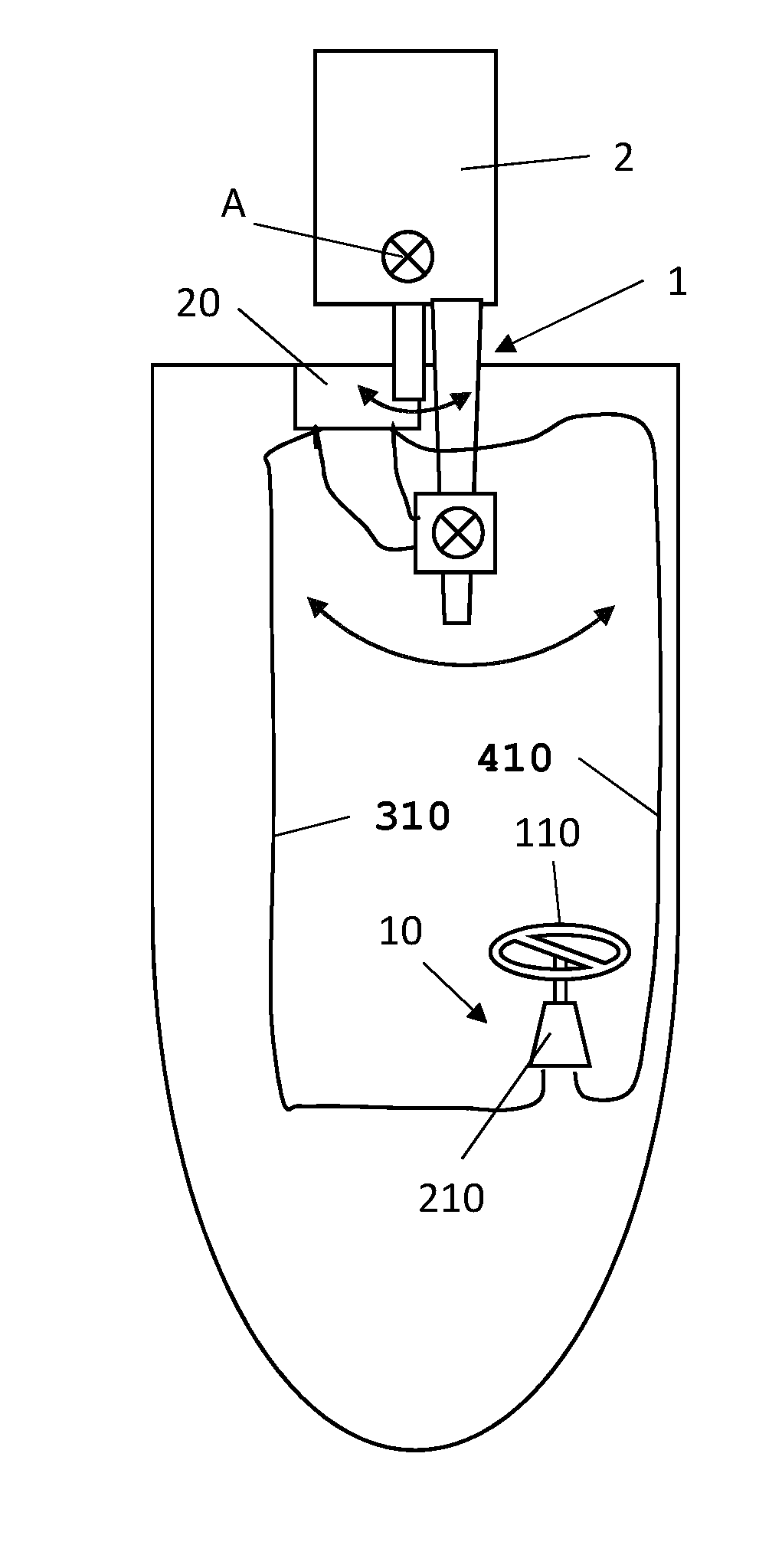
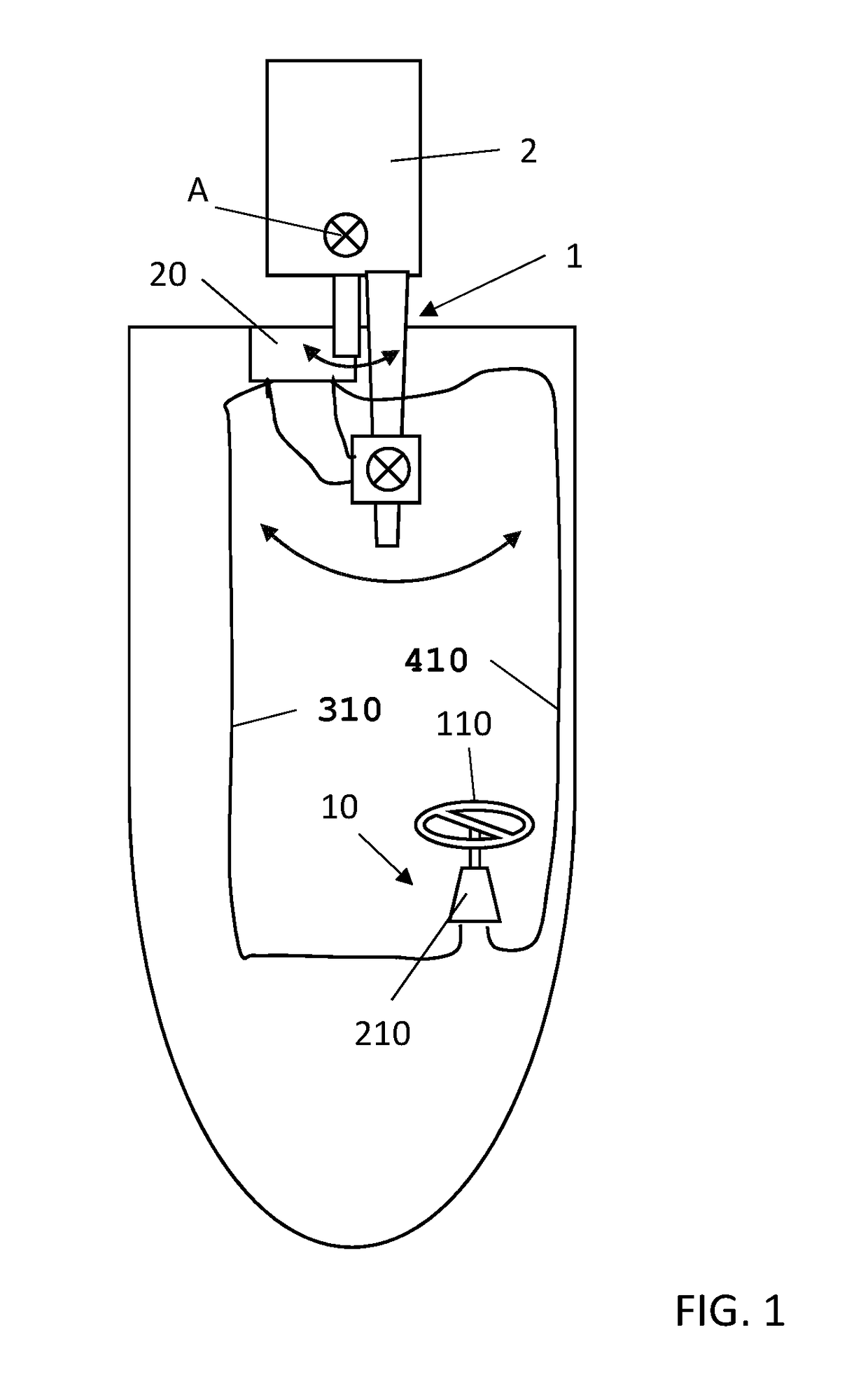
[0050]FIG. 1 schematically shows a watercraft with an outboard motor 2 fastened to the transom. A steering tiller 1 is fastened to the outboard motor 2 and can be provided with different control members for controlling different functionalities of the motor, such as the number of revolutions of the motor, the forward direction or the idle condition, or the position of the motor with respect to the transom.

[0051]The steering tiller 1 is integral with the mounted motor so as to rotate together with the tiller about a steering axis denoted by A.

[0052]FIG. 1 depicts an additional steering control station 10 having a steering wheel 110, and a generator of signals controlling an actuating unit 20.

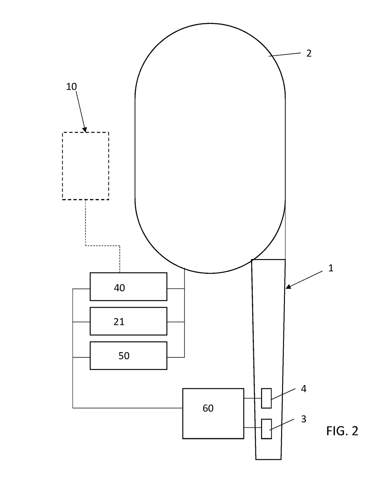
[0053]FIG. 2 shows the system in greater details.

[0054]According to the present invention, control members 3 and 4 are associated to the steering tiller 1.

[0055]The characteristics of the invention that will be disclosed below can be provided as an alternative or in combination with one another.

[...


PUM


Abstract

A steering control system for a watercraft includes a pivoting steering tiller manually operated and operatively connected to a direction changing member acting on or into the water, such as a rudder blade or an outboard motor; and a system locking the steering tiller in the steering position, which can be activated for keeping the tiller in a predetermined pivoting position and deactivated for allowing the tiller to be moved in a pivoting position to carry out a change in direction. According to the invention the locking system is switchable by way of switching actuators that are controlled by a control member provided on the arm.

Description

FIELD OF THE INVENTION[0001]The present invention relates to a steering control system for a watercraft comprising a pivoting steering tiller manually operated and operatively connected to a direction changing member acting on or into the water, such as a rudder blade or an outboard motor; and means locking the steering tiller in the steering position, which can be activated for keeping said tiller in a predetermined pivoting position and can be deactivated for allowing said tiller to be moved in a pivoting position to carry out a change in direction.BACKGROUND OF THE INVENTION[0002]Systems of this type are known, for example from patent U.S. Pat. No. 7,325,507. This document provides for the steering action, namely, the force exerted on the steering tiller or on the steering arm of the motor through said tiller, to be exerted manually by an operator. The system only exerts an action locking the motor or the rudder and therefore the steering tiller when a change in direction, that i...

Claims


Application Information

Patent Timeline
Patent Type & Authority Applications(United States)
IPC IPC(8): B63H25/38B63H20/00
CPCB63H25/38B63H2025/024B63H21/265B63H20/12B63H20/10
Inventor GAI, MARCELLAPAGANI, ENRICO
Owner ULTRAFLEX
Why Eureka
Try Eureka