LED Lighting Module for Plant Factory and LED Lighting Device for Plant Factory having Same Mounted thereon

a technology of led lighting and plant factory, which is applied in the direction of semiconductor devices for light sources, light and heating apparatus, and saving energy measures, etc., can solve the problems of unfavorable plant growth of 3-band radiation lamps, large power consumption, and high cost of red-chips, so as to reduce the risk of change in the target condition, enhance plant growth in plant factories, and remove the effect of the risk of chang

Inactive Publication Date: 2017-04-13
FUTURE LIGHT CO LTD
View PDF6 Cites 4 Cited by
  • Summary
  • Abstract
  • Description
  • Claims
  • Application Information

AI Technical Summary

Benefits of technology

[0024]The LED lighting technology for plant factories of the present invention may provide advantages as set below.
[0025](1) Plant growth in plant factories may be enhanced by implementing the light intensity having peaks in blue-series wavelength band (450 nm) and red-series wavelength band (660 nm) even though incorporating LED blue-chips which are cheaper than conventional LED red-chips.
[0026](2) Growth efficiency of plants may be enhanced respectively by selectively and differently blending red-series phosphor, red-series plus green-series phosphor, or red-series plus yellow-series phospor so as to implement the light intensity by wa

Problems solved by technology

However, the 3-band radiation lamps are disadvantageous in that power consumption is large and life-time is short.
Further, the 3-band radiation lamps are unfavorable to plant growth.
However,

Method used


Image

  • LED Lighting Module for Plant Factory and LED Lighting Device for Plant Factory having Same Mounted thereon
  • LED Lighting Module for Plant Factory and LED Lighting Device for Plant Factory having Same Mounted thereon
  • LED Lighting Module for Plant Factory and LED Lighting Device for Plant Factory having Same Mounted thereon

Examples


second embodiment

[0090]As shown in FIG. 15, in the second embodiment, light intensity graph moves to zone ① in approximately 510 nm wavelength band so as to form an upward convex shape.

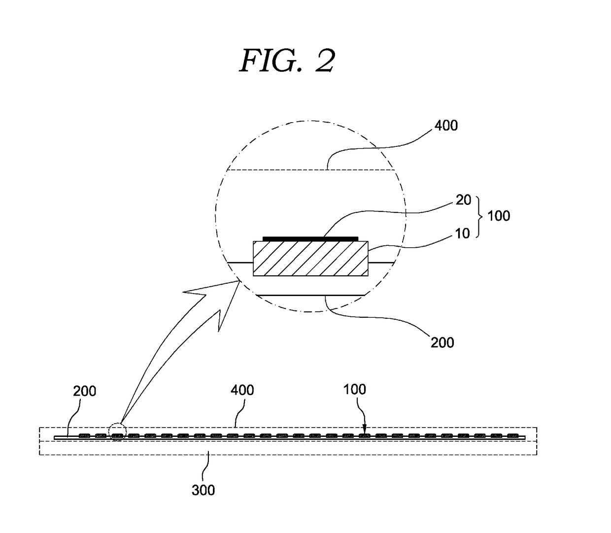
[0091]FIG. 16 shows an emission spectrum for specific wavelength bands of LED lighting apparatuses for plant factories according to a third embodiment of mixing phosphor of the present invention. Referring to FIG. 16, the mixing phosphor 20 according to the third embodiment is made by blending red-series and yellow-series RY-phosphor. The mixing phosphor 20 is applied on surface of the blue-chip light-source 10 so as to form particular light intensity by wavelength band which are confirming to specific plant groups.

[0092]It is preferable that the light intensity shows a first local maximum in 430 nm-470 nm wavelength band which is crucial to plant growth for particular plants, and further show a second local maximum in 550 nm-730 nm wavelength band which is also crucial to plant growth.

[0093]Further, it is preferable ...

third embodiment

[0094]As shown in FIG. 16, in the third embodiment, light intensity graph moves to zone ② in approximately 510 nm wavelength band so as to form an upper-left convex shape.

[0095]As also shown in FIGS. 14 to 16, in the first to third embodiments, the value of light intensities in the first and second local maximums may increase or decrease by the amount of the mixing phosphor 20 which is applied on the surface of the blue-chip light-source 10.


PUM


Abstract

The present invention relates to technology to implement a technique of managing light intensity by each wavelength band for a light apparatus at a low price, whereby the light intensity is suitable for plant growth. In the present invention, cheaper LED blue-chips are incorporated instead of more expensive LED red-chips which are conventionally incorporated in plant factories, which let the production cost of lighting apparatus for plant factories reduced. By applying red-series, green-series and yellow-series phosphors onto the LED blue-chips, light intensity by wavelength band of lighting apparatuses may meet target conditions which are favorable to plant growth. Further, work environment may be improved by reducing eyestrain due to red light-source, and growth efficiency of plants may be enhanced by improving wavelength characteristics of lighting apparatuses.

Description

FIELD OF THE INVENTION[0001]The present invention relates to technology to implement a technique of managing light intensity by each wavelength band for a light apparatus at a low price, whereby the light intensity is suitable for plant growth.[0002]In the present invention, cheaper LED blue-chips are incorporated instead of more expensive LED red-chips which are conventionally incorporated in plant factories, which let the production cost of lighting apparatus for plant factories reduced. By applying red-series, green-series and yellow-series phosphors onto the LED blue-chips, light intensity by wavelength band of lighting apparatuses may meet target conditions which are favorable to plant growth. Further, work environment may be improved by reducing eyestrain due to red light-source, and growth efficiency of plants may be enhanced by improving wavelength characteristics of lighting apparatuses.[0003]More specifically, the present invention implements LED lighting modules and LED l...

Claims


Application Information

Patent Timeline
IPC IPC(8): F21V19/00H01L33/48F21S4/28H01L33/50A01G7/04F21V3/04
CPCF21V19/003A01G7/045F21V3/0409F21Y2115/10H01L33/502H01L33/486F21S4/28H01L33/504Y02P60/14
Inventor CHO, SUNG-BIN
Owner FUTURE LIGHT CO LTD
Why Eureka
Try Eureka