

Heat sink assembly
a heat sink and assembly technology, applied in indirect heat exchangers, light and heating equipment, etc., can solve the problems of not meeting environmental safety requirements, unable to achieve comprehensive heat absorbing and dissipation effects, and low heat dissipation efficiency of prior heat designs, so as to enhance the overall heat dissipation efficiency of the heat sink assembly and quick dissipation
- Summary
- Abstract
- Description
- Claims
- Application Information
AI Technical Summary
Benefits of technology
Problems solved by technology
Method used
Image

Examples
first embodiment
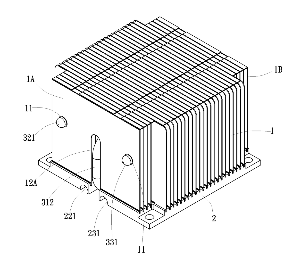
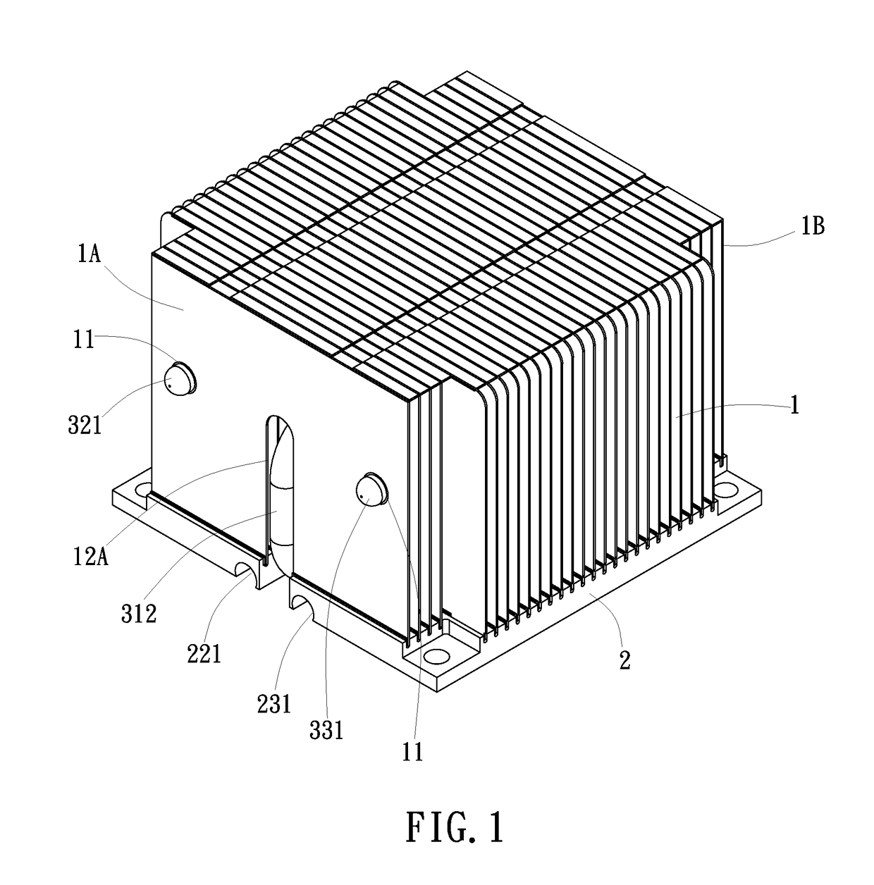
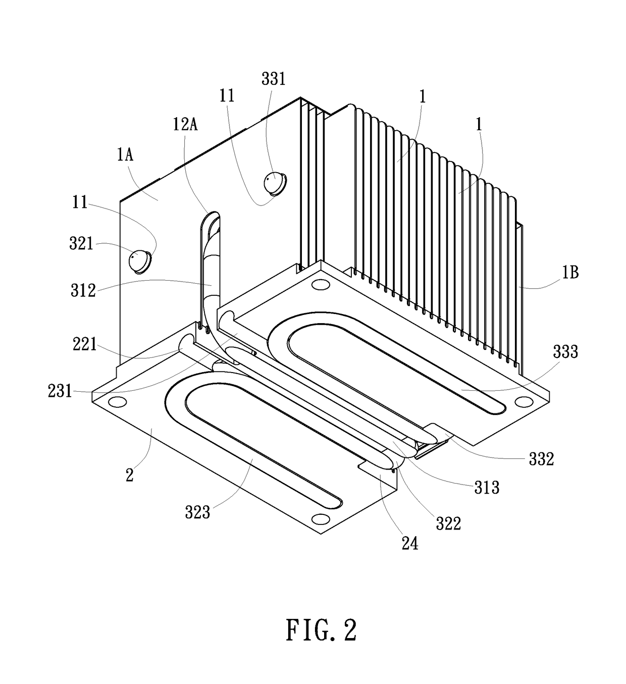
[0023]Referring to FIGS. 1-9, a heat sink assembly in accordance with the present is shown. The heat sink assembly comprises a plurality of cooling fins 1, a base block 2 and at least three heat pipes 31,32,33 (see FIG. 8). The cooling fins 1 are installed in a top wall of the base block 2 (see FIGS. 1-3), each comprising a plurality of tight-fit mounting holes 11 for the mounting of the heat pipes 31,32,33.
[0024]The base block 2, as illustrated in FIG. 9, comprises a straight mounting groove 21 located at a bottom wall thereof and two U-shaped mounting grooves 22,23 symmetrically disposed at two opposite lateral sides relative to the straight mounting groove 21. The straight mounting groove 21 can be located at the midpoint of the bottom wall of the base block 2. The U-shaped mounting grooves 22,23 can be respectively located at two opposite lateral sides of the bottom wall of the base block 2.
[0025]The three heat pipes 31,32,33, as illustrated in FIG. 8, include one U-shaped heat ...
second embodiment
[0036]In this second embodiment, the base block 2a further comprises a spacer portion 25a formed of a part of the bottom wall thereof between the two mating notches 24a,24b, and a plurality of mounting through holes 26a respectively disposed at four corners thereof and opposing front and rear ends of the spacer portion 25a for fastening to a circuit board (not shown) by respective fastening members.
[0037]The mounting arrangement between the cooling fins 1,1′ and the base block 2,2a is achieved using a tight fitting technique that is of the known art and not within the scope of the present invention, therefore, no further detailed description in this regard will be necessary.
[0038]In the heat sink assembly in accordance with the present invention, the cooling fins 1,1′, the base block 2,2a and the three heat pipes 31,32,33 (or four heat pipes 31a,31b,32a,33a) are respectively fastened together using a tight fitting technique, therefore, when thermal expansion occurs, the overall stru...
PUM
 Abstract
Description
Claims
Application Information