Image reading apparatus, image forming apparatus, image forming system, image forming method, and non-transitory computer-readable recording medium which stores image forming control program therein

a technology of image reading and control program, which is applied in the direction of electrical equipment,pictoral communication, etc., can solve the problems of colorimetric accuracy not being guaranteed, colorimeters cannot accurately measure the color and be calibrated, and image scanners are not excellent in color reproducibility. to achieve the effect of accurate and efficient measurement of color

Active Publication Date: 2017-04-13
KONICA MINOLTA INC
View PDF1 Cites 7 Cited by
  • Summary
  • Abstract
  • Description
  • Claims
  • Application Information

AI Technical Summary

Benefits of technology

[0022]The present invention is designed with respect to the above described circumstances which are considered as the background, and an object is to provide: an image reading apparatus which can accurately and efficiently measure the color by using different image detecting sections, even when there is a failure in the image; an image forming apparatus; an image forming system; an image forming method; and a non-transitory computer-readable recording medium which stores an image forming control program therein.

Problems solved by technology

However, the image scanner is not excellent in color reproducibility, and accordingly has also such a feature that colorimetric accuracy cannot be guaranteed.
By the way, when the colorimeter measures the color, in the case where there are inconsistencies in density, dirt, a scratch and the like in the patch, there is a problem that the colorimeter cannot correctly measure the color and be calibrated.
However, when the patch length becomes long, the number of sheets of a chart necessary for calibration increases, and there is a problem that waste paper results in being produced per one calibration.
In addition, the colorimeter is not suitable for determining an image failure.
However, as has been described above, when there is a failure portion in the patch, it becomes difficult to appropriately calibrate the line sensor on the basis of a result of reading by the colorimeter.
In Japanese Patent Laid-Open No. 2007-30340, the image forming apparatus needs to form a patch in another place so as to avoid an area of an abnormal image, and move the place for measuring the color there; and accordingly results in needing a movement mechanism for carrying the colorimeter to a matching place every time, and causing an increase of the cost.
In addition, the image forming apparatus is an apparatus which changes the patch position to another place based on a premise that the area of the abnormal image is specified and is stably abnormal, and cannot cope with an accidentally abnormal image, dirt and the like.
In addition, in Japanese Patent Application Laid-Open No. 2009-124458, the method determines a predicted value, based on the colorimetric result of a patch in a correct state, and when the value is different from the predicted value, determines that the patch is not appropriate, and accordingly firstly needs to measure the color of the patch in the correct state; and when the colorimetry by the line sensor is not performed with reliability, the predicted value also becomes inappropriate.
In addition, there is a problem that the abnormality cannot be surely eliminated, considering that the predicted value contains a prediction error.
Furthermore, when the patch becomes inappropriate, the present patch becomes incapable of being used, and then the patch needs to be printed again, which causes a problem that paper for adjustment results in being wasted.

Method used


Image

  • Image reading apparatus, image forming apparatus, image forming system, image forming method, and non-transitory computer-readable recording medium which stores image forming control program therein
  • Image reading apparatus, image forming apparatus, image forming system, image forming method, and non-transitory computer-readable recording medium which stores image forming control program therein
  • Image reading apparatus, image forming apparatus, image forming system, image forming method, and non-transitory computer-readable recording medium which stores image forming control program therein

Examples


Embodiment Construction

[0068]Hereinafter, an embodiment of the present invention will be described with reference to the drawings. However, the scope of the invention is not limited to the illustrated examples.

[0069]One embodiment of the present invention will be described below with reference to the attached drawings.

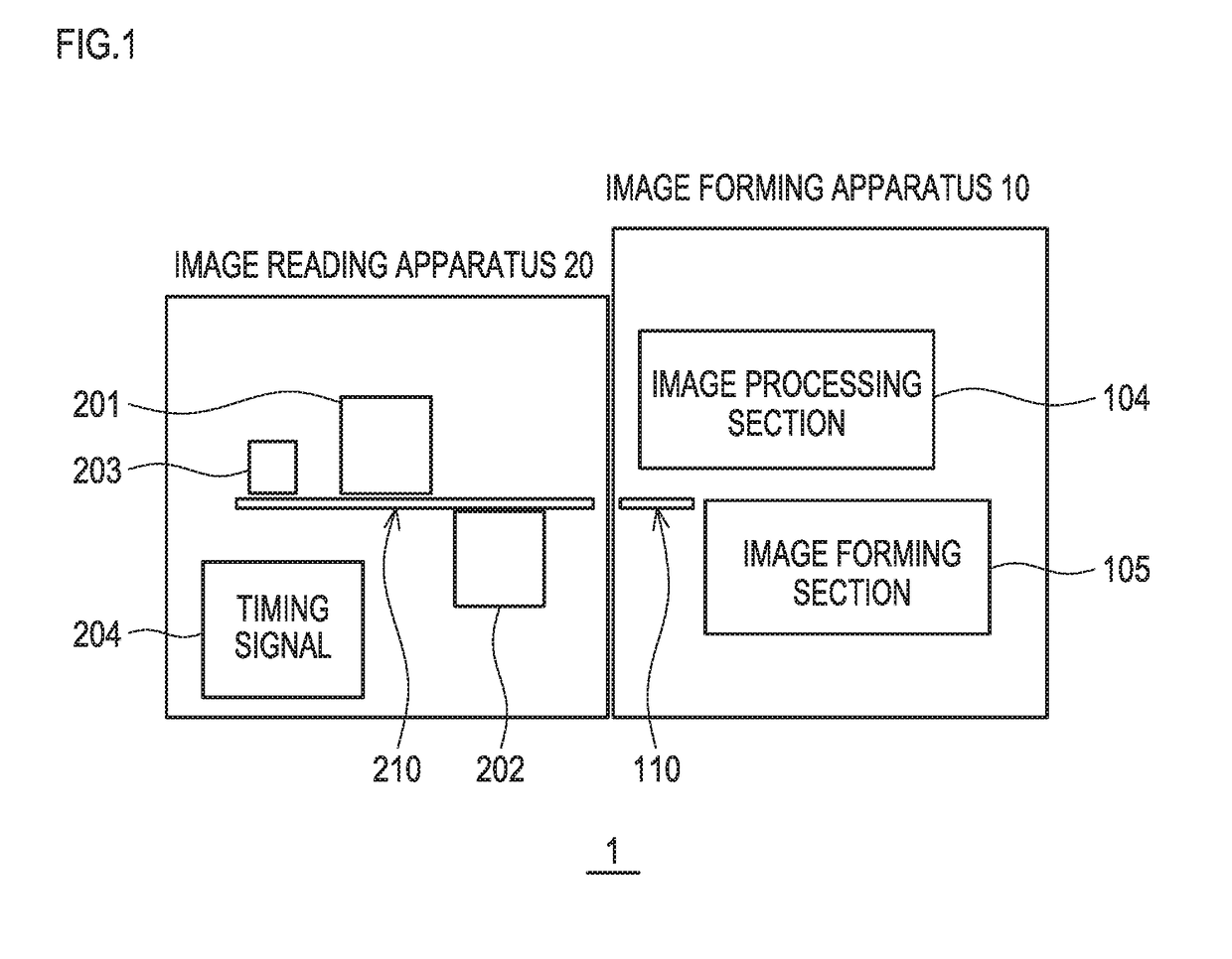
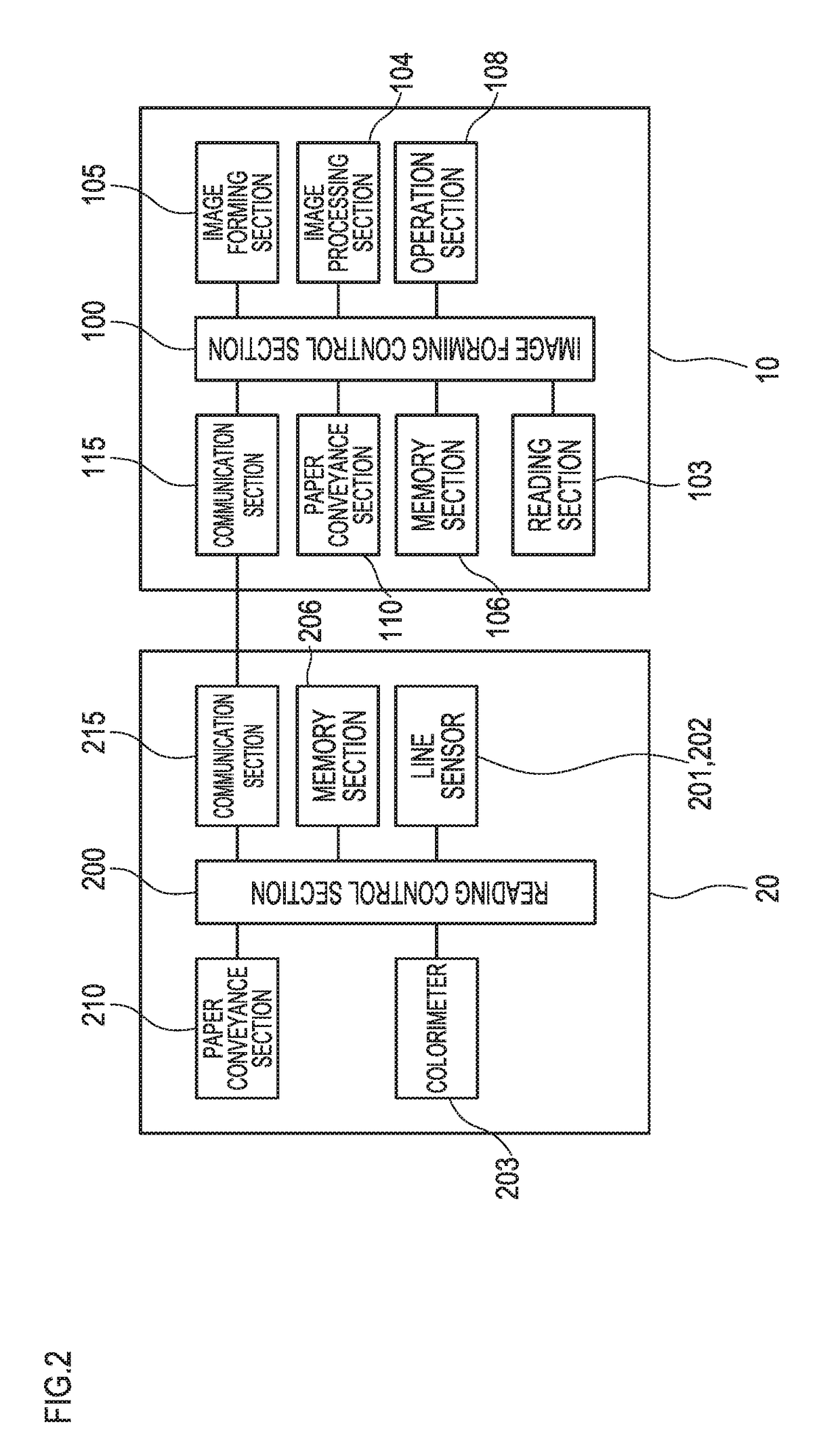
[0070]An image forming system 1 includes an image forming apparatus 10 which forms an image on paper, and an image reading apparatus 20 which detects the image formed on the paper; and in this embodiment, the image reading apparatus 20 is electrically and mechanically connected to the downstream side of the image forming apparatus 10. However, in the present invention, it is not indispensable that the image forming apparatus and the image reading apparatus are connected to each other in-line, but the image forming apparatus and the image reading apparatus may have an off-line relationship, and may deliver data concerning the colorimetry to and receive the data from each other.

[0071]The image...


PUM


Abstract

An image forming apparatus includes: an image forming section that forms an image; and an image forming control section that acquires information on a detection result of the image by a first image detecting section which has relatively higher failure detection accuracy than that of a second image detecting section, and information on a detection result of the image by the second image detecting section which has relatively higher color measurement accuracy than that of the first image detecting section, wherein the image forming control section acquires second image detection information in a region that has been detected by the second image detecting section and in which an exclusion detection region has been removed, based on the exclusion detection region that has been determined to contain a failure in the image, by first image detection information based on the detection result of the first image detecting section.

Description

[0001]The present U.S. patent application claims a priority under the Paris Convention of Japanese patent application No. 2015-201130 filed on Oct. 9, 2015, the entirety of which is incorporated herein by references.BACKGROUND OF THE INVENTION[0002]Field of the Invention[0003]This invention relates to: an image reading apparatus that can acquire each of detection results of a first image detecting section which reads an image on a transfer medium and has high failure detection accuracy, and a second image detecting section which reads the image and has high color detection accuracy; an image forming apparatus; an image forming system; an image forming method; and a non-transitory computer-readable recording medium which stores an image forming control program therein.[0004]Description of the Related Art[0005]In an image forming apparatus such as a printer and a multifunctional machine, an image forming apparatus is conventionally known which prints a color patch, detects a patch of ...

Claims


Application Information

Patent Timeline
Patent Type & Authority Applications(United States)
IPC IPC(8): H04N1/00
CPCH04N1/00816H04N2201/0094H04N1/00819H04N1/00002H04N1/00023
Inventor HAYASHI, KENICHIFUTAMI, HIROYUKITAKAHASHI, KATSUNORINARA, TAKASHINOUTOMI, TATSUHIRO
Owner KONICA MINOLTA INC
Why Eureka
Try Eureka