Lubricating apparatus for rotating shaft

Active Publication Date: 2017-04-20
KAWASAKI MOTORS LTD
View PDF11 Cites 5 Cited by
  • Summary
  • Abstract
  • Description
  • Claims
  • Application Information

AI Technical Summary

Benefits of technology

[0015]With the above-mentioned configuration, oil scraped by the gear portion of the third rotating shaft can be supplied to the first rotating shaft and the second rotating shaft without using any oil pumping means such as an oil pump. Moreover, even when the shaft center line of the second rotating shaft is located above the upper end portion of the gear portion of the third rotati

Problems solved by technology

However, when the rotating shafts is located high, the amount of supplied lubricating oil decreases.
In addition, high-load and high-speed rotation of

Method used


Image

  • Lubricating apparatus for rotating shaft
  • Lubricating apparatus for rotating shaft
  • Lubricating apparatus for rotating shaft

Examples


second embodiment

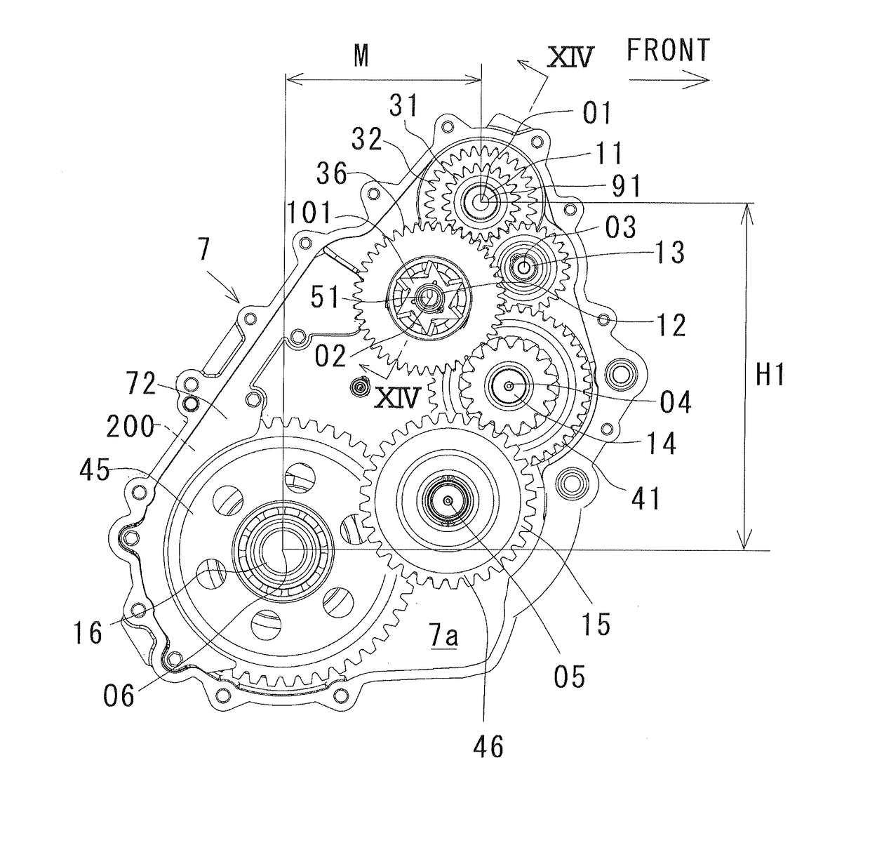
[0085]FIG. 13 and FIG. 14 illustrate a second embodiment. The second embodiment is different from the first embodiment in that, as illustrated in FIG. 13, a distance M between the shaft center line O1 of the input shaft 11 and the shaft center line O6 of the final gear shaft 16 in the longitudinal direction is much smaller than the distance in the first embodiment illustrated in FIG. 3. Further, the final gear 45 is used as a gear portion for scraping oil stored in the bottom of the transmission case 7. That is, the final gear shaft 16 is adopted as a third rotating shaft (output shaft) for scraping oil as recited in claims. The configuration other than the difference in the second embodiment is the same as the configuration in the first embodiment, and the same parts as those in the first embodiment are given the same reference numerals.

[0086]In FIG. 13, the power take-off shaft 14, the speed-change shaft 12, the reverse idle shaft 13, and the input shaft 11 are arranged in this or...


PUM


Abstract

A lubricating apparatus of the present invention is applied to a transmission having a plurality of rotating shafts, and includes a first rotating shaft having a first oil passage, a second rotating shaft, and an impeller fixed to an axial end of the first rotating shaft. The impeller is arranged in a first oil storage chamber communicated with an outlet of the first oil passage. The impeller rotates with the first rotating shaft to scatter oil, and supplies the oil to the second rotating shaft.

Description

CROSS-REFERENCE TO RELATED APPLICATIONS[0001]The disclosure of U.S. patent application Ser. No. 14 / 010,890 filed on Aug. 27, 2013 including specification, drawings and abstract is incorporated herein by reference in its entirety.BACKGROUND OF THE INVENTION[0002]Field of the Invention[0003]The present invention relates to a lubricating apparatus for rotating shaft, and in particular, a lubricating apparatus for supplying oil to a plurality of rotating shafts arranged in a case.[0004]Description of the Related Art[0005]The lubricating apparatus is mounted in, for example, a gear transmission to lubricate bearings of the rotating shafts, engaged portions of gears, and fitted portions of the gears and the rotating shafts. Examples of a method of supplying oil include a method of pumping lubricating oil compressed in an oil pump to each portion to be lubricated via passages inner of rotating shafts and a case wall, a method of scraping oil accumulated on a bottom of a case with gears and...

Claims


Application Information

Patent Timeline
IPC IPC(8): F16H57/04
CPCF16H57/043F16H57/0436F16H57/0471F16H57/045F16H57/0423F16H57/0441F16H57/0434
Inventor ITOO, SEIJIHAMADA, AYUMINISHIMURA, SHIGERU
Owner KAWASAKI MOTORS LTD
Why Eureka
Try Eureka